Air way structure and air conditioner
A technology for air ducts and air duct openings, which is applied in the field of air duct structures and air conditioners. It can solve problems such as unreasonable design of the volute tongue structure, impact on customer experience, vibration and abnormal noise, etc., and achieve a sense of user experience and vortex wind. Few phenomena, reducing the effect of snail tongue vortex wind problem
- Summary
- Abstract
- Description
- Claims
- Application Information
AI Technical Summary
Problems solved by technology
Method used
Image

Examples
Embodiment Construction
[0040] It should be noted that, in the case of no conflict, the embodiments in the present disclosure and the features in the embodiments can be combined with each other.
[0041] In addition, the terms "first", "second" and the like mentioned in the embodiments of the present disclosure are only used for distinguishing descriptions, and cannot be understood as indicating or implying relative importance.
[0042] The present disclosure will be described in detail below with reference to the accompanying drawings and embodiments.
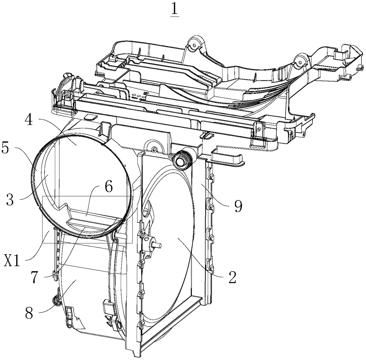
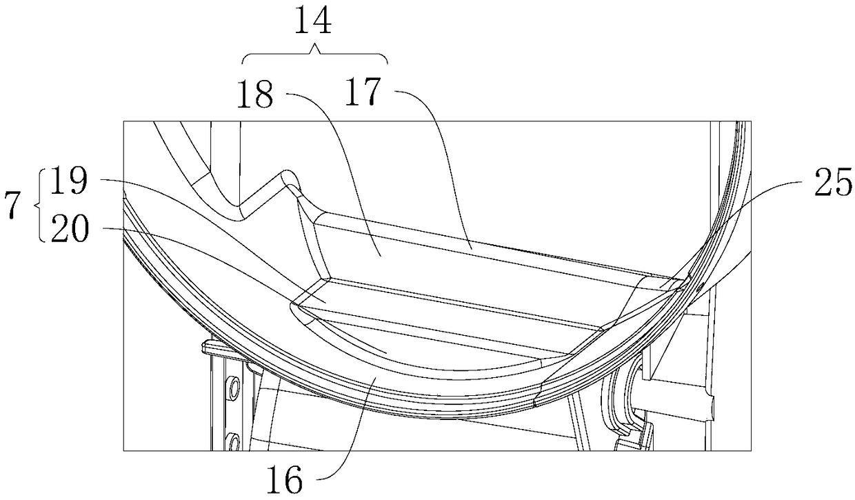
[0043] figure 1 It is a structural schematic diagram of the air duct structure 1 described in this embodiment. figure 2 for figure 1 Enlarged image at X1 in the middle. Please refer to figure 1 and figure 2 , this embodiment discloses an air duct structure 1 , which includes a volute cover 8 and a volute seat 9 . The volute cover 8 and the volute seat 9 are detachably connected to form the inner air channel 2 and the outer air channel 3 which...
PUM
 Abstract
Description
Claims
Application Information
 - R&D
- Intellectual Property
- Life Sciences
- Materials
- Tech Scout
- Unparalleled Data Quality
- Higher Quality Content
- 60% Fewer Hallucinations
Browse by: Latest US Patents, China's latest patents, Technical Efficacy Thesaurus, Application Domain, Technology Topic, Popular Technical Reports.
© 2025 PatSnap. All rights reserved.Legal|Privacy policy|Modern Slavery Act Transparency Statement|Sitemap|About US| Contact US: help@patsnap.com