Laser level meter module automatic line-adjusting equipment

A laser level and equipment technology, applied in the direction of instruments, measuring instruments, active optical measuring devices, etc., can solve the problems of complex operation methods, low production efficiency, and high operator dependence, and achieve saving of operating area, high precision, and equipment structure simple effect

Inactive Publication Date: 2018-12-21
中山市天志光电科技有限公司
View PDF0 Cites 2 Cited by
  • Summary
  • Abstract
  • Description
  • Claims
  • Application Information

AI Technical Summary

Problems solved by technology

[0003] However, the existing operation method for adjusting the laser line has the following disadvantages: First, the process requirements for the laser line are visually measured by human eyes, resulting in low precision of the laser line
The second is that the human eye staring at the laser for a long time will cause visual fatigue, which will lead to misjudgment and easy to produce work errors
The third is that the operation is highly dependent on the operator, and the enterprise needs to spend a lot of labor costs
Fourth, the operation requires a large area
Fifth, the operation method is complicated, resulting in low production efficiency

Method used


Image

  • Laser level meter module automatic line-adjusting equipment
  • Laser level meter module automatic line-adjusting equipment
  • Laser level meter module automatic line-adjusting equipment

Examples


Embodiment Construction

[0021] The specific embodiments of the present invention will be further described below in conjunction with the accompanying drawings. It should be noted here that the description of these embodiments is used to help understand the present invention, but does not constitute a limitation to the present invention. In addition, the technical features involved in the various embodiments of the present invention described below can be combined with each other as long as they do not conflict with each other.

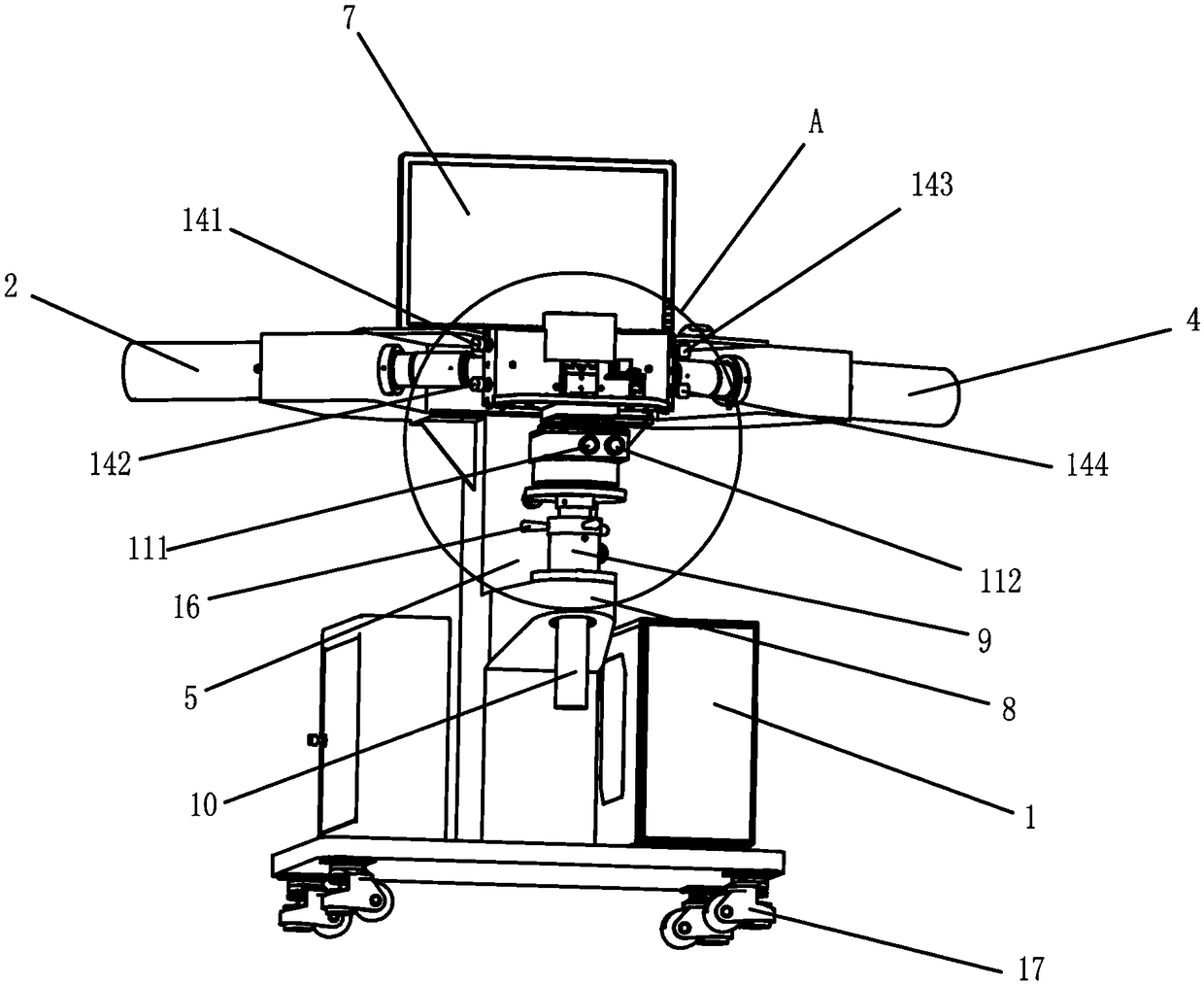
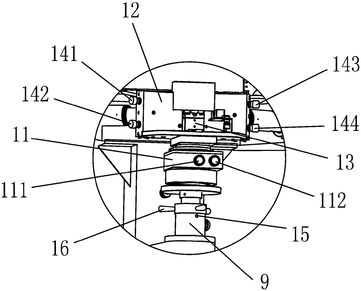
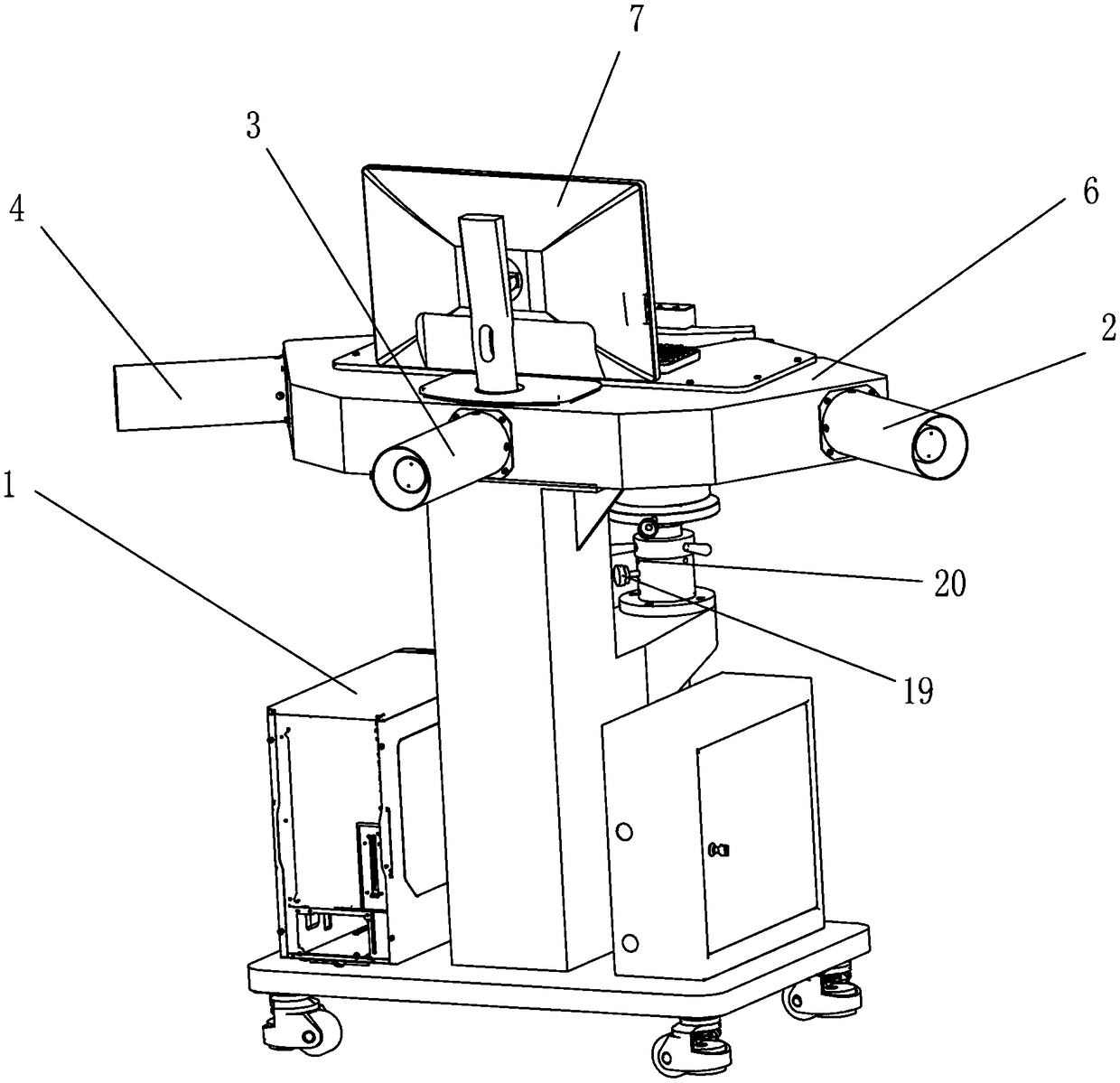
[0022] Such as Figure 1-7 As shown, a laser level module automatic line adjustment equipment includes a computer host 1, a collimator, and a device body 5. The device body 5 is provided with a workbench 6, and the workbench 6 is placed with a display screen 7, a keyboard, and a mouse. Such as computer equipment, the above-mentioned collimator is installed on the workbench 6. The collimator is used to capture the laser line 18 emitted by the laser level module 13, the collimato...


PUM


Abstract

The invention relates to the technical field of photoelectricity, and discloses laser level meter module automatic line-adjusting equipment. The laser level meter module automatic line-adjusting equipment comprises a computer host, a collimator and an equipment body. A workbench is arranged on the equipment body, a display screen is arranged on the workbench, the collimator is installed on the workbench, a boss is arranged on the middle portion of the equipment body, and a shaft sleeve is arranged on the boss. The laser level meter module automatic line-adjusting equipment further comprises acolumn body, a balancing platform matched with the column body and a laser level meter operation platform matched with the balancing platform, the column body penetrates through the shaft sleeve, thebalancing platform is provided with an inclined hand wheel and a rotating hand wheel, the laser level meter operation platform is provided with a laser level meter module, and the laser level meter operation platform is provided with focusing screws on two sides. The laser level meter module automatic line-adjusting equipment is simple in structure, the operation mode is simple and easy to understand, the precision of a laser line can be automatically analyzed with data, a laser line with higher accuracy can be obtained, a camera is replaced with the collimator to capture laser lines, and theoperation area is saved.

Description

Technical field [0001] The invention relates to the field of optoelectronic technology, in particular to an automatic line adjustment equipment for a laser level module module. Background technique [0002] The laser level is a measuring tool used in surveying, engineering, decoration, production and processing and other fields. Its function is to emit a horizontal line determined by gravity and a vertical line perpendicular to the horizontal line. The user uses the laser line or the plane formed by the intersection of the laser line and the laser line as a reference to work. After the laser line emitted by the laser level module, the laser line needs to be adjusted. The existing adjustment method is: stick three horizontal targets at a distance of 5 meters from the worktable of the laser level module. Bullseye, the laser line is irradiated on the three horizontal targets, and the three horizontal targets get the 3 points of the laser line. Use the camera to capture the three la...

Claims


Application Information

Patent Timeline
Patent Type & Authority Applications(China)
IPC IPC(8): G01C15/00
CPCG01C15/004
Inventor 代彪陈能兵凡后军
Owner 中山市天志光电科技有限公司
Why Eureka
Try Eureka