A key switch with the function of pressing and producing sound
A key and switch technology, applied in the field of key switches with the function of pressing and sounding, can solve the problems of lack of pressing feel and insufficient sound-emitting structure design, and achieve the effects of improving user experience, high structural stability, and triggering sensitivity and precision.
- Summary
- Abstract
- Description
- Claims
- Application Information
AI Technical Summary
Problems solved by technology
Method used
Image
Examples
Embodiment 1
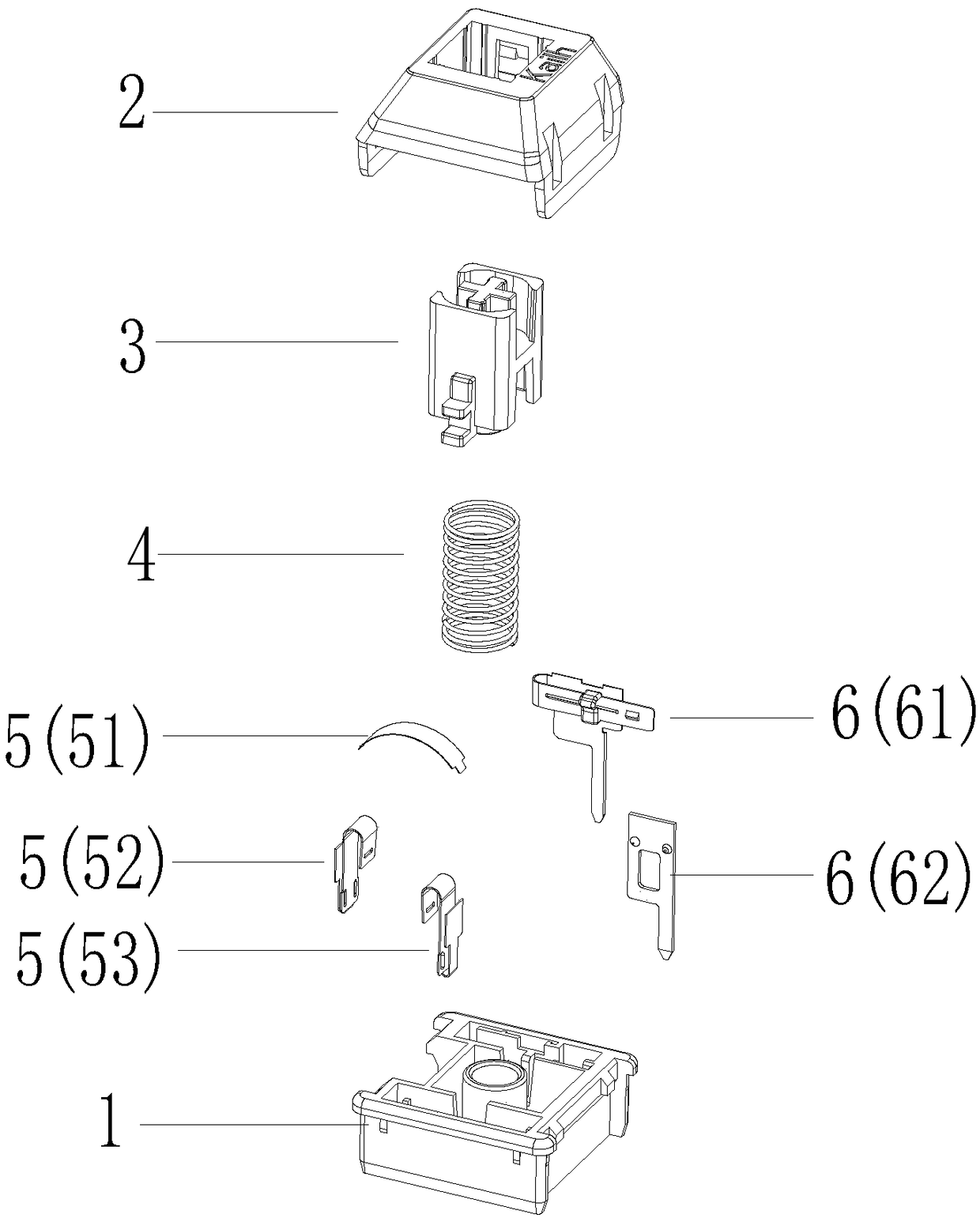
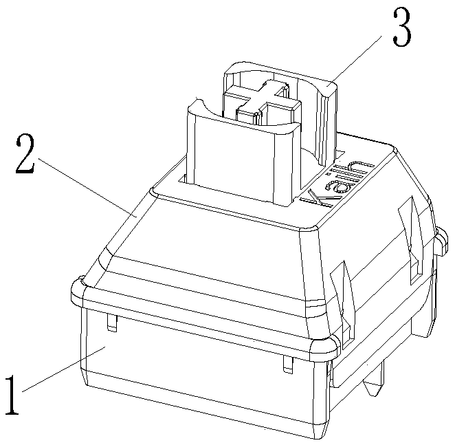
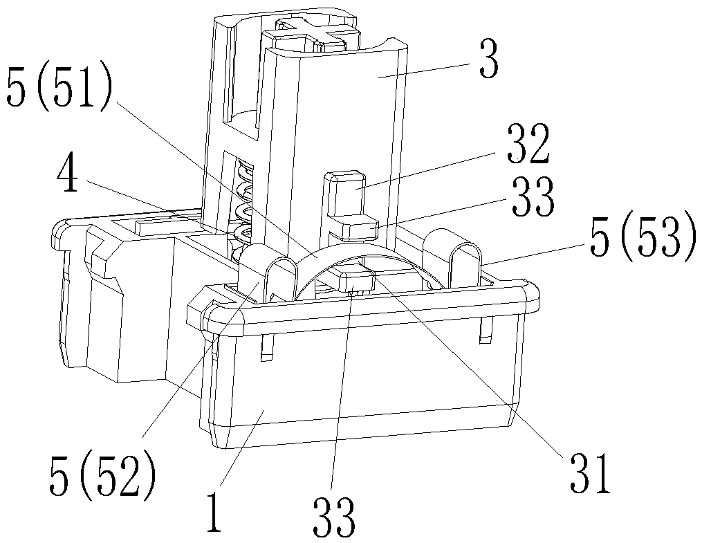
[0040] Please refer to Figure 1 to Figure 6 , the embodiment of the present invention provides a key switch with the function of pressing and sounding, which includes a base 1 and a cover 2 arranged above the base 1. The cover 2 is combined with the base 1 to form an accommodating cavity. A guide core 3 and an elastic member 4 located below the guide core 3 are respectively arranged in the accommodating chamber, and the elastic member 4 provides elastic restoring force for pressing the guide core 3 up and down; An opening through which the upper end of the guide core 3 passes. The key switch of this embodiment also includes an elastic sound-generating component 5 arranged in the accommodating cavity and on the side of the guide core 3, and a side notch 31 is formed on the side of the guide core 3, such as Figure 4 and Figure 5 shown; as Figure 4 and Figure 6 As shown, the elastic sounding component 5 includes an upper elastic piece 51 passing through the side notch 31...
Embodiment 2
[0057] The main difference between this embodiment and Embodiment 1 is that the conduction component of the key switch of this embodiment is different from that of Embodiment 1. The conduction component of this embodiment is a magnetic conduction component 7, such as Figure 15 to Figure 17 As shown, the magnetic conduction component 7 includes a magnet 71 disposed in the positioning post 35 and a magnetic inductor 722 disposed below the magnet 71, wherein a supply magnet 71 is provided on the lower end of the positioning post 35 upwards. An upper groove 351 is embedded, and a plurality of limiting blocks 352 located at the lower end of the magnet 71 protrude inward on the inner wall of the upper groove 351 . The magnet 71 is limited by the upper groove 351 , so that the magnet 71 moves up and down with the guide core 3 moving up and down.
[0058] In this embodiment, the magnetic sensor 72 can be arranged on the PCB board, and usually the base 1 is arranged on the upper end s...
PUM
 Abstract
Description
Claims
Application Information
 - R&D
- Intellectual Property
- Life Sciences
- Materials
- Tech Scout
- Unparalleled Data Quality
- Higher Quality Content
- 60% Fewer Hallucinations
Browse by: Latest US Patents, China's latest patents, Technical Efficacy Thesaurus, Application Domain, Technology Topic, Popular Technical Reports.
© 2025 PatSnap. All rights reserved.Legal|Privacy policy|Modern Slavery Act Transparency Statement|Sitemap|About US| Contact US: help@patsnap.com


