A miniaturize filter strip dielectric antenna

A dielectric antenna and strip technology, applied in the field of communication, can solve the problems of large medium size and no filtering function, and achieve the effect of reducing the medium size, improving the out-of-band suppression performance, and reducing mutual coupling.

Active Publication Date: 2018-12-21
南通大学技术转移中心有限公司
View PDF7 Cites 2 Cited by
  • Summary
  • Abstract
  • Description
  • Claims
  • Application Information

AI Technical Summary

Problems solved by technology

[0004] Therefore, the dielectric size of the existing low-permittivity filter dielectric antenna (HEM dielectric mode) is relatively large, and most designs of the existing high-permittivity dielectric antenna (TM11 cavity mode) reduce the dielectric size, but do not have filtering function, while the dielectric antenna with filtering function has the problem of large dielectric size

Method used


Image

  • A miniaturize filter strip dielectric antenna
  • A miniaturize filter strip dielectric antenna
  • A miniaturize filter strip dielectric antenna

Examples


Embodiment 1

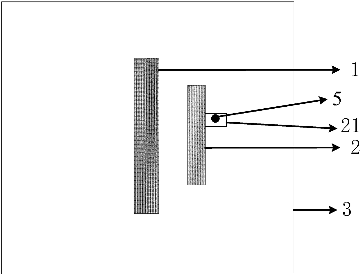
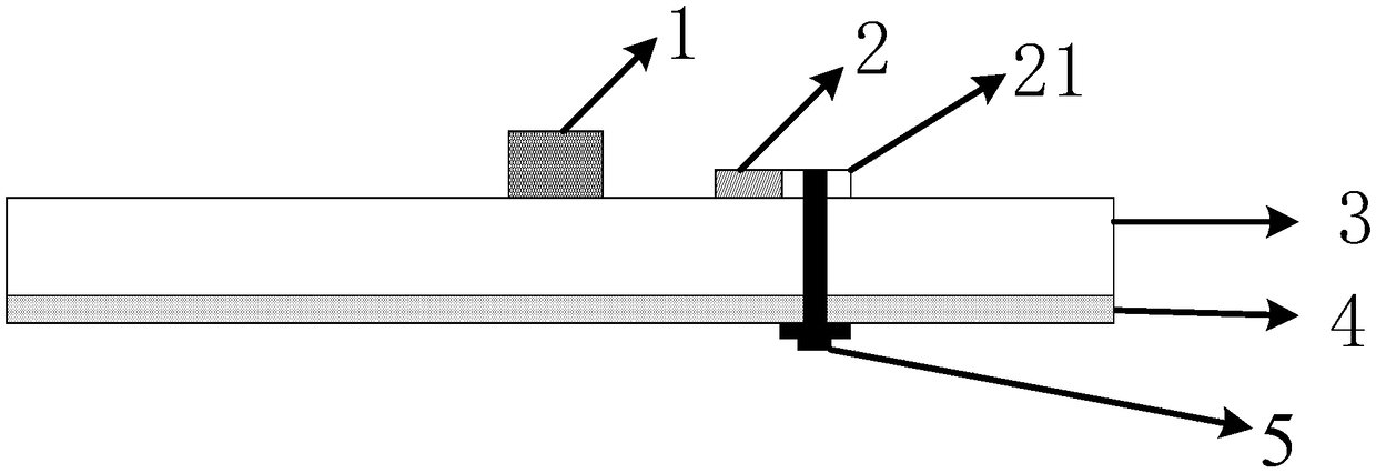
[0025] An embodiment of the present invention provides a miniaturized filter strip dielectric antenna, see figure 1 and figure 2 , including: a strip dielectric sheet 1, a microstrip line 21, a half-wavelength microstrip line 2, a probe 5, a dielectric substrate 3 and a metal ground 4;

[0026] The strip-shaped dielectric sheet 1, the microstrip line 21 and the half-wavelength microstrip line 2 are arranged on one side of the dielectric substrate 3, and the metal ground 4 is arranged on the other side of the dielectric substrate 3 ;

[0027] The probe 5 is arranged on the metal ground 4, and the probe 5 is connected to the half-wavelength microstrip line 2 through the microstrip line 21 to transmit signals to the half-wavelength microstrip line 2; the half-wavelength microstrip line 2 is coupled with the strip-shaped dielectric sheet 1, so as to couple the signal to the strip-shaped dielectric sheet 1 and excite the TM on the strip-shaped dielectric sheet 1 δ1 cavity mold....


PUM


Abstract

The invention discloses a miniaturized filter strip dielectric antenna, which comprises a strip dielectric sheet, a microstrip line, a half-wavelength microstrip line, a probe, a dielectric substrateand a metal ground. The strip-shaped dielectric sheet, the microstrip line and the half-wavelength microstrip line are arranged on one side of the dielectric substrate, and the metal is arranged on the other side of the dielectric substrate; The probe is arranged on the metal ground, and the probe is connected with the half-wavelength microstrip line through the microstrip line to transmit a signal to the half-wavelength microstrip line; The half-wavelength microstrip line is coupled to the strip dielectric sheet to couple the signal to the strip dielectric sheet to excite a TM delta 1 cavitymode on the strip dielectric sheet. The invention can realize the filtering function, and the medium size is greatly reduced.

Description

technical field [0001] The invention relates to the field of communication technology, in particular to a miniaturized filter strip dielectric antenna. Background technique [0002] Dielectric antennas and filter antennas are antenna types identified from the material and function of the antenna. The main body of the dielectric antenna is composed of a dielectric, and its conductor loss is low, so it has the advantages of low loss, high radiation efficiency, and high degree of design freedom. The filter antenna has both filtering and antenna receiving and sending functions. Therefore, compared with the traditional antenna cascaded filter method, the filter antenna can effectively reduce the demand for filters in the system, reduce loss, improve efficiency, and reduce the frequency of adjacent antennas. Mutual coupling between. Both antennas have been extensively researched and applied, so combining the dielectric antenna and the filter antenna to form a filter dielectric an...

Claims


Application Information

Patent Timeline
Patent Type & Authority Applications(China)
IPC IPC(8): H01Q1/36H01Q1/48H01Q1/50
CPCH01Q1/36H01Q1/48H01Q1/50
Inventor 施金徐凯张威曹青华陈燕云陈建新杨永杰
Owner 南通大学技术转移中心有限公司
Why Eureka
Try Eureka