High-birefringence hollow-core anti-resonance optical fiber based on resonant coupling effect enhancement

A high birefringence, resonant coupling technology, used in cladding fibers, Sagnac effect gyroscopes, optics, etc., can solve the difficulty of fiber optic gyroscopes to meet the requirements of high-precision inertial navigation applications, and reduce the reciprocity of polarization-maintaining fiber loops It can solve problems such as stability and affect the measurement accuracy of fiber optic gyroscopes, so as to achieve the effects of flexible structural design, improved birefringence coefficient and stable performance.

Pending Publication Date: 2022-01-07
TIANJIN NAVIGATION INSTR RES INST
View PDF7 Cites 1 Cited by
  • Summary
  • Abstract
  • Description
  • Claims
  • Application Information

AI Technical Summary

Problems solved by technology

At present, the traditional polarization-maintaining optical fiber is the core raw material of the fiber optic gyroscope, which has some inherent physical problems determined by the transmission medium, such as poor environmental adaptability, large non-reciprocal optical noise, etc. Inertial navigation application requirements, the magneto-optical Faraday effect caused by the magnetic field, the Shupe effect caused by the temperature, and the elastic-optic effect caused by the stress will all produce parasitic phase differences in the traditional polarization-maintaining fiber optic gyroscope, reducing the polarization-maintaining fiber. The reciprocity of the ring affects the measurement accuracy of the fiber optic gyroscope

Method used


Image

  • High-birefringence hollow-core anti-resonance optical fiber based on resonant coupling effect enhancement
  • High-birefringence hollow-core anti-resonance optical fiber based on resonant coupling effect enhancement
  • High-birefringence hollow-core anti-resonance optical fiber based on resonant coupling effect enhancement

Examples


Embodiment Construction

[0022] The structure of the present invention will be further described below in conjunction with the accompanying drawings and through embodiments. It should be noted that this embodiment is illustrative rather than limiting.

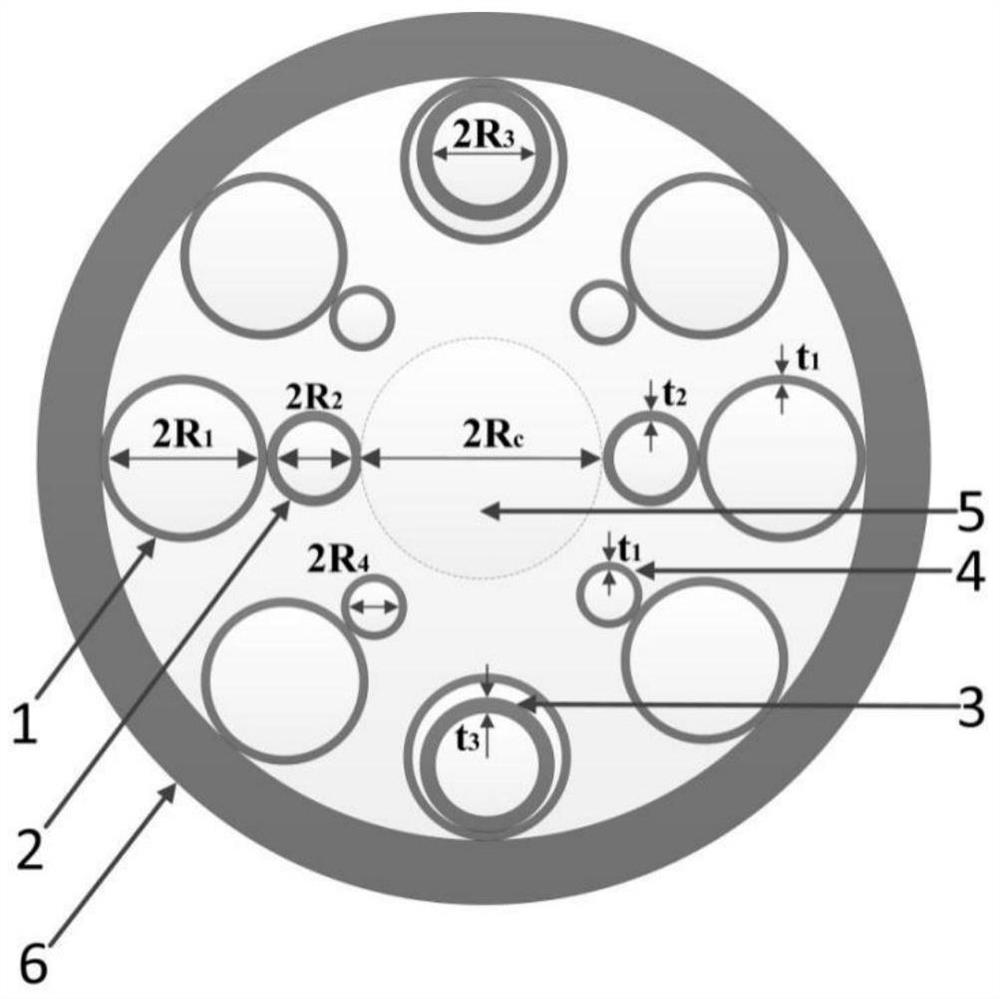
[0023] figure 1 Be embodiment 1: a kind of high birefringence hollow core anti-resonant optical fiber end face structure schematic diagram based on resonance coupling effect enhancement, in the figure, the inner cladding thin-walled microcapillary 1 (away from the fiber core) that is directly affixed to the optical fiber outer cladding, internal diameter 2R 1 , the wall thickness is t 1; Microcapillary 2 circumscribed with the outermost circle of microcapillary (away from the core) (participating in resonance coupling), inner diameter 2R 2 , the wall thickness is t 2 ; Microcapillary 3 (participating in resonance coupling) inscribed with the outermost circle of microcapillary (away from the fiber core), with an inner diameter of 2R 3 , the wall thi...


PUM


Abstract

The invention relates to a high-birefringence hollow-core anti-resonance optical fiber based on resonant coupling effect enhancement. The high-birefringence hollow-core anti-resonance optical fiber comprises a cladding region and an inner fiber core region, the inner fiber core area is an air area or a vacuum area, the cladding area comprises an outer cladding and an inner cladding, and the outer cladding is a hollow cylinder with a certain thickness; the inner cladding is composed of a plurality of circles of micro capillary tubes which are arranged in the outer cladding and are sequentially connected from inside to outside; the outermost circle of micro capillary tubes are uniformly distributed in the circumferential direction and are fixedly connected with the inner wall surface of the outer cladding; the micro capillary tubes in the same circle of other circles are arranged in a spaced mode, the number of the micro capillary tubes in the other circles is two less than that of the micro capillary tubes in the outermost circle, and the two lacked micro capillary tubes are arranged at the two positions with the included angle of 180 degrees; the two micro capillary tubes opposite to the lacking positions of the micro capillary tubes in other circles in the outermost circle of micro capillary tubes and/or the two micro capillary tubes forming 90-degree included angles with the lacking positions of the two micro capillary tubes in the innermost circle of micro capillary tubes are micro capillary tubes of a composite double-layer structure. The high-birefringence hollow-core anti-resonance optical fiber has a large birefringence coefficient.

Description

technical field [0001] The invention belongs to the technical field of photonic crystal fiber optic gyro, and in particular relates to a high-birefringence hollow-core anti-resonant fiber based on enhanced resonance coupling effect. Background technique [0002] Fiber optic gyroscope is one of the most typical applications in the field of fiber optic sensing. It has the advantages of all solid state, high reliability, simple process, high precision, large dynamic range, fast startup, and long life. It is widely used in attitude reference systems, inertial navigation, etc. And guidance system and strapdown north seeking and vehicle positioning and orientation system. In recent years, the major progress made in the research of fiber optic gyroscopes has fully demonstrated and verified its performance advantages and development potential. At present, the development of fiber optic gyroscopes has gradually leaped from the tactical level and the navigation level to the strategic ...

Claims


Application Information

Patent Timeline
Patent Type & Authority Applications(China)
IPC IPC(8): G02B6/02G01C19/64
CPCG02B6/02342G02B6/02328G01C19/64
Inventor 梁鹄赵小明罗巍娄癸阳李茂春颜苗马林马骏
Owner TIANJIN NAVIGATION INSTR RES INST
Why Eureka
Try Eureka