A power management device based on power line communication technology

A technology of power management device and power line communication, which is applied in substation/distribution device casing, substation/switchgear cooling/ventilation, electrical components, etc., which can solve the problems of reduced service life, component damage, and time-consuming , to facilitate wiring, increase service life, and improve shock absorption effect

Inactive Publication Date: 2018-12-21
安徽国锦电力工程有限公司
View PDF10 Cites 5 Cited by
  • Summary
  • Abstract
  • Description
  • Claims
  • Application Information

AI Technical Summary

Problems solved by technology

[0005] Aiming at the deficiencies of the prior art, the present invention provides a power management device based on power line communication technology, which has the advantages of long service life, convenient wiring, etc., and solves the problem that the existing power management device has a single structure and function, and does not have the ability to control its internal components. The function of device protection, the internal components of the equipment work too long or when the device vibrates, it will cause certain damage to the components, thereby reducing the service life of the device. On the other hand, the power management device of communication technology and When the main line of the control line is connected, the connection method requires the main line to be connected to the internal component board of the device, so that the cover of the device needs to be opened to perform wiring on the distribution board. This method not only consumes a lot of time, but also Problems that affect the power experience on the main line

Method used


Image

  • A power management device based on power line communication technology
  • A power management device based on power line communication technology
  • A power management device based on power line communication technology

Examples


Embodiment Construction

[0025] The following will clearly and completely describe the technical solutions in the embodiments of the present invention with reference to the accompanying drawings in the embodiments of the present invention. Obviously, the described embodiments are only some, not all, embodiments of the present invention. Based on the embodiments of the present invention, all other embodiments obtained by persons of ordinary skill in the art without making creative efforts belong to the protection scope of the present invention.

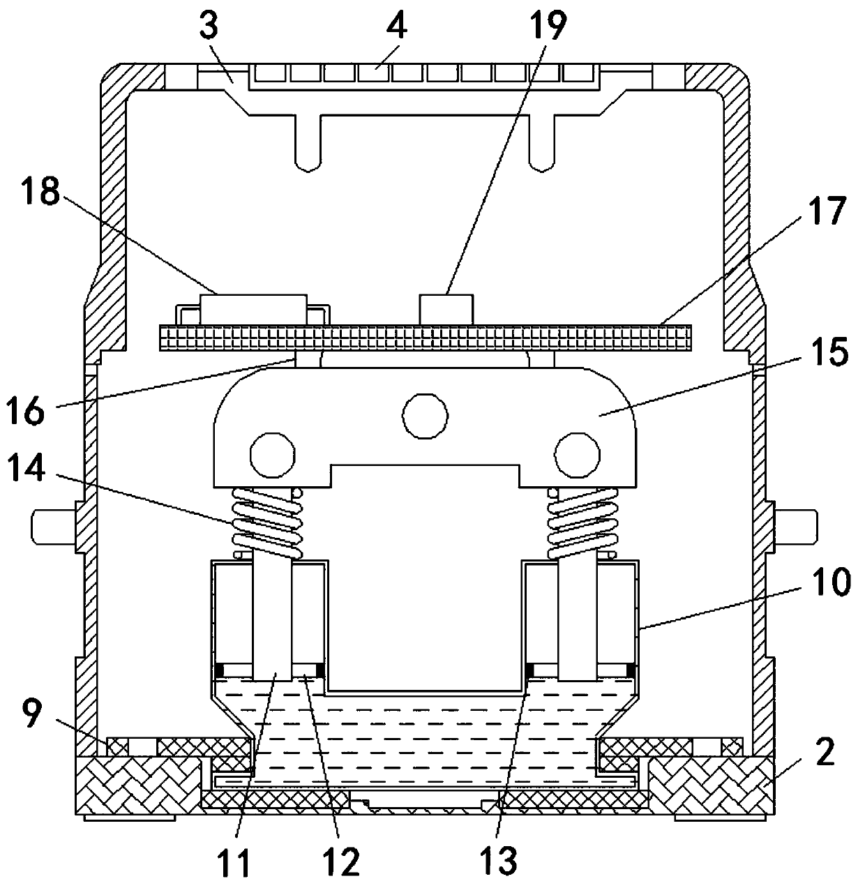
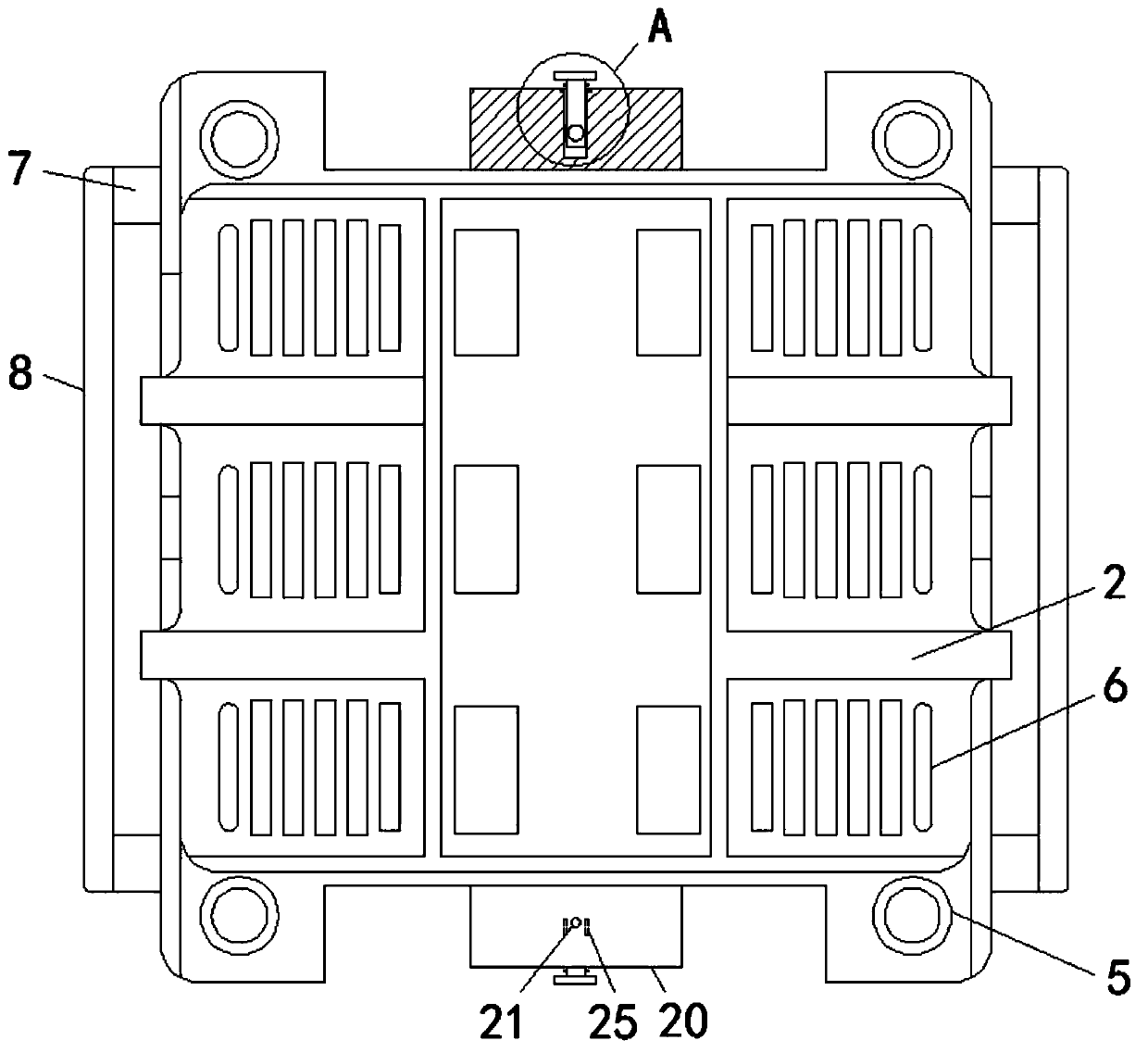
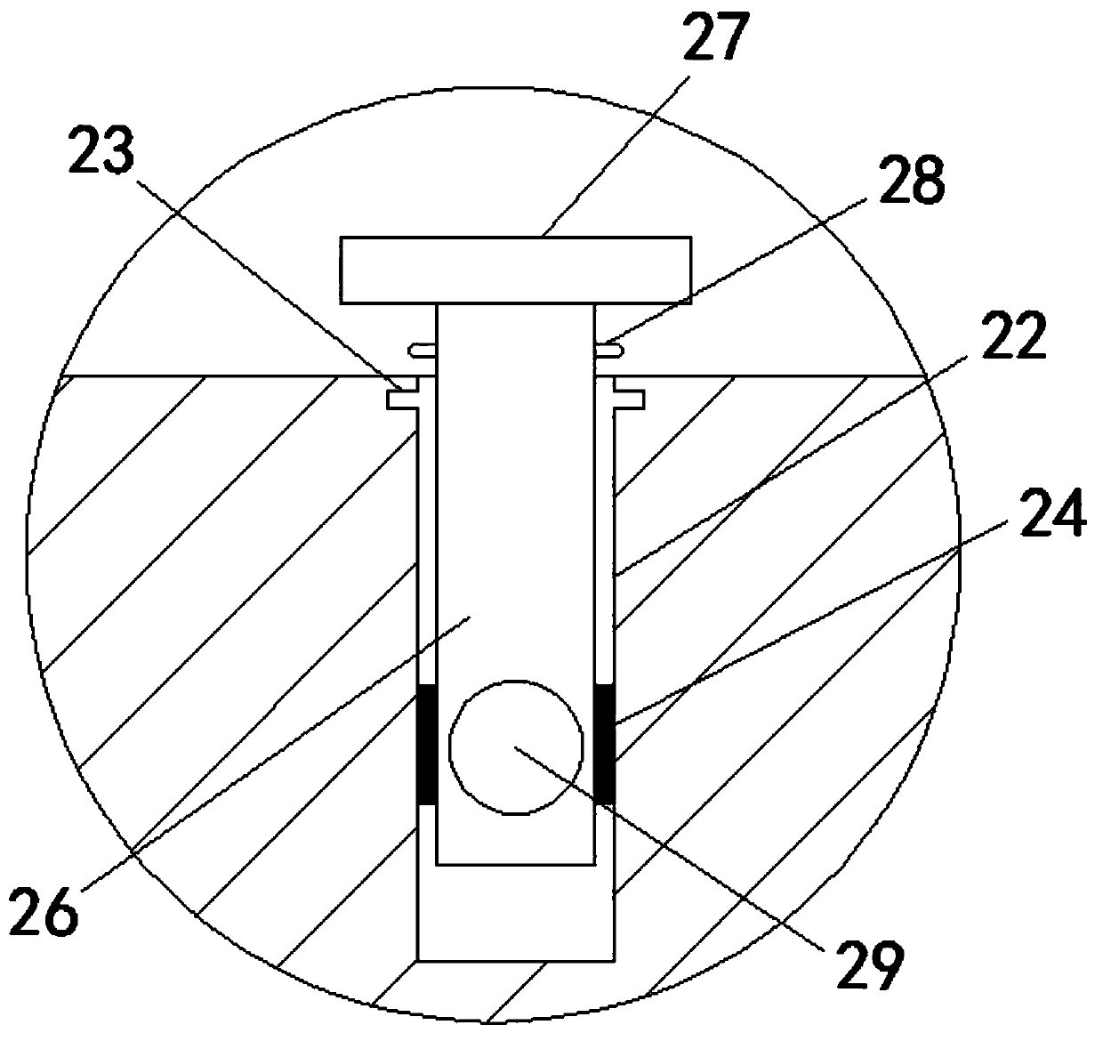
[0026] see Figure 1-4, a power management device based on power line communication technology, comprising a housing 1, a bottom cover 2 is fixedly installed on the bottom of the housing 1, a cover plate 3 is clipped on the top of the housing 1, a keyboard 4 is fixedly installed on the top of the cover plate 3, and a bottom cover 2 is fixedly installed on the bottom of the housing 1. The bottom of the cover 2 is fixedly equipped with a suction cup 5, and the c...


PUM


Abstract

The invention relates to the technical field of power management equipment, and discloses a power management device based on power line communication technology, comprising a housing, wherein a bottomcover is fixedly installed on the bottom of the housing. According to the power management device based on the power line communication technology, a hydraulic cartridge fixedly mounted through the interior of the enclosure, and through the pressure bar inside the hydraulic tank, A switch board is fixedly mounted on the top of the pressing block, when the main controller or other components on the switchboard are subjected to external vibration or impulse, the vibration force is transferred to the pressing block through the connected block, and the spring fixedly installed at the bottom of the pressing block plays the role of damping vibration of the pressing block, The hydraulic oil inside the hydraulic box is compressed by the pressure block through the position limiting block during the vibration process, and the hydraulic oil plays a shock absorbing role, thereby improving the shock absorbing effect of the device. The pressure bar is arranged inside the hydraulic box and is provided with a finite position block and a sealing rubber.

Description

technical field [0001] The invention relates to the technical field of power management equipment, in particular to a power management device based on power line communication technology. Background technique [0002] At present, the use of electricity has brought about a complete change in people's life style, and has also promoted the substantial development and progress of industry and technology. Various electrical equipment and consulting equipment are flooding people's living environment, bringing considerable For the convenience of operation, these electrical equipment are usually designed to be permanently connected to the power supply line to avoid damage due to repeated plugging. When it is abnormal, the current and voltage of the device will also be unstable, which will easily cause a short circuit. If it is not detected in time, it will easily affect the safety of electricity use. [0003] In order to solve similar problems in communication equipment, people hav...

Claims


Application Information

Patent Timeline
Patent Type & Authority Applications(China)
IPC IPC(8): H02B1/26H02B1/28H02B1/54H02B1/56H02G3/04
Inventor 陆彬彬安在兵吴海峰
Owner 安徽国锦电力工程有限公司
Why Eureka
Try Eureka