
A heat dissipation device and a heat dissipation method of a power supply isolation module

A power isolation and heat dissipation device technology, which is applied in the direction of electrical components, electrical equipment structural parts, modification through conduction heat transfer, etc., can solve the problems that cannot meet the requirements of heat dissipation, high heat flux density, large thermal resistance, etc., and achieve faster Heat loss, good thermal conductivity, effect of increasing fluidity

Inactive Publication Date: 2018-12-21
SHANDONG CHAOYUE DATA CONTROL ELECTRONICS CO LTD
View PDF4 Cites 0 Cited by
  • Summary
  • Abstract
  • Description
  • Claims
  • Application Information

AI Technical Summary

Problems solved by technology

Due to the fully enclosed design of the case, the power isolation module generates a lot of heat. If it is simply installed by attaching the case, the thermal resistance in the conduction process is relatively large, which makes it impossible to use the large area of ​​the bottom case for heat dissipation.
Excessive local heat flux density will also lead to excessively high body temperature at the palm rest, which will affect the user experience. Therefore, the original heat dissipation method can no longer meet the heat dissipation requirements.

Method used


Image

  • A heat dissipation device and a heat dissipation method of a power supply isolation module
  • A heat dissipation device and a heat dissipation method of a power supply isolation module

Examples


Embodiment

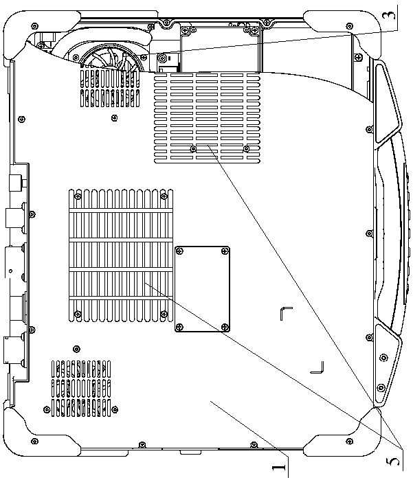
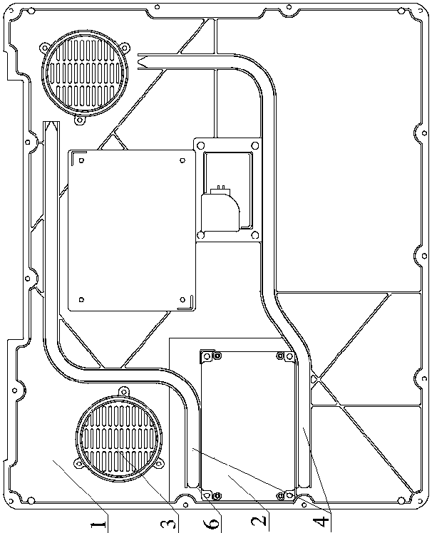
[0029] Such as figure 1 and figure 2 As shown, the power isolation module heat dissipation device of the present invention includes a chassis, a power isolation module 2 , a fan 3 , two heat dissipation pipes 4 and heat dissipation fins 5 .

[0030] The power isolation module 2 and the fan 3 are respectively fixed on the chassis bottom shell 1 . Two grooves 6 are opened on the bottom case 1 of the chassis, and two heat dissipation pipes 4 are respectively welded in the grooves 6 . Both cooling pipes 4 are in contact with the power isolation module 2 . The air outlet of the cooling pipe 4 corresponds to the air inlet of the fan 3 . Both the power isolation module 2 and the chassis bottom shell 1 are made of aluminum alloy. Radiating fins 5 are fixed on the outer side of the chassis bottom shell 1 , and the heat dissipation direction of the cooling fins 5 is consistent with the airflow direction of the air inlet of the fan 3 . The cooling fins 5 are disconnected from the m...


PUM


Abstract

The invention discloses a heat dissipation device and a heat dissipation method of a power supply isolation module, belonging to the technical field of heat dissipation of an electric function module.The heat dissipation device of the power supply isolation module of the invention comprises a chassis, a power supply isolation module, a plurality of heat dissipation tubes and a fan. The power supply isolation module and the fan are arranged on the bottom shell of the chassis, and the heat dissipation tubes are arranged on the bottom shell and are in contact with the power supply isolation module. The heat dissipation device of the power supply isolation module of the invention can uniformly dissipate heat, and has good popularization and application value.

Description

technical field [0001] The invention relates to the technical field of heat dissipation of electrical function modules, and specifically provides a heat dissipation device and a heat dissipation method for a power isolation module. Background technique [0002] In order to ensure equipment safety and wide voltage input, a power isolation module is added inside the equipment. Since the chassis adopts a fully enclosed design, the power isolation module generates a lot of heat. If it is simply installed by sticking to the chassis, the thermal resistance in the conduction process is relatively large, which makes it impossible to use the large area of ​​the bottom case for heat dissipation. Excessive local heat flux density will also lead to excessively high body temperature at the palm rest, which will affect the user experience. Therefore, the original heat dissipation method can no longer meet the heat dissipation requirements. Contents of the invention [0003] The technic...

Claims


Application Information

Patent Timeline
Patent Type & Authority Applications(China)
IPC IPC(8): H05K7/20H05K5/04
CPCH05K5/04H05K7/20136H05K7/20336H05K7/2039H05K7/20418
Inventor 张长强梁记斌亓慧兴
Owner SHANDONG CHAOYUE DATA CONTROL ELECTRONICS CO LTD
Learn More