Centrifugal compressor

A technology of centrifugal compressors and impellers, applied in mechanical equipment, engine manufacturing, machines/engines, etc., can solve problems such as pressure loss, achieve the effect of reducing peeling and improving compression performance

Active Publication Date: 2018-12-21
IHI CORP
View PDF7 Cites 2 Cited by
  • Summary
  • Abstract
  • Description
  • Claims
  • Application Information

AI Technical Summary

Problems solved by technology

[0004] However, in the conventional centrifugal compressor, especially at the operating point on the large flow side, the flow of the fluid flowing in from the discharge portion of the scroll to the winding start portion is separated from the inner surface of the flow path, and there is a possibility that a flow caused by the separation may occur. Possibility of pressure loss caused by

Method used


Image

  • Centrifugal compressor
  • Centrifugal compressor
  • Centrifugal compressor

Examples


Embodiment Construction

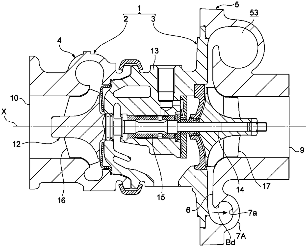
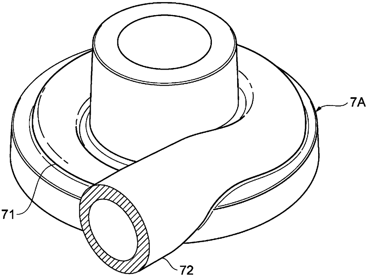
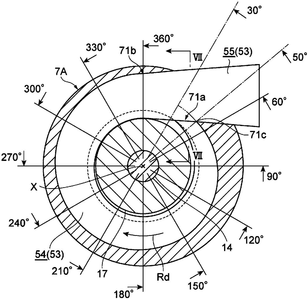
[0022] A centrifugal compressor according to one embodiment of the present invention includes: an impeller, and a scroll arranged around the impeller and forming a flow path including a scroll flow path along the rotation direction of the impeller, and the scroll includes: The discharge part connected to the winding end part of the scroll flow path, and the winding start part connected to the discharge part, the winding start part is connected at an obtuse angle with respect to the discharge part on the suction side in the direction along the rotation axis of the impeller. .

[0023] In the centrifugal compressor of this embodiment, the winding start portion is connected at an obtuse angle to the discharge portion on the suction side in the direction along the rotation axis of the impeller. Therefore, the fluid flowing into the winding start portion from the discharge portion is less likely to be separated, which contributes to the improvement of the compression performance. ...


PUM


Abstract

A centrifugal compressor is provided with a compressor impeller (17) for pumping a fluid and a scroll (7A) that is arranged around the compressor impeller (17) and that has formed therein a flow pathincluding a scroll flow path (54) along the direction of rotation (Rd) of the compressor impeller (17). The scroll (7A) is provided with: a discharge section (72) connected to a winding end section (71b) of the scroll flow path (54); and a winding start section (71a) connected to the discharge section (72). The winding start section (71a) is connected at an obtuse angle (alfa1) with respect to thedischarge section (72) on the intake side in a direction following the rotational axis (X) of the compressor impeller (17).

Description

technical field [0001] The present disclosure relates to centrifugal compressors. Background technique [0002] There is known a centrifugal compressor in which a spiral scroll is disposed on an outer peripheral portion of an impeller. In this type of centrifugal compressor, the fluid compressed by the impeller is introduced into the scroll through the diffuser, and the scroll is appropriately decelerated to achieve static pressure recovery (see JP-A-2012-140900). A spiral flow path is formed in the scroll, and a discharge portion is provided at a winding end portion of the flow path. The winding start portion of the flow path is connected to the discharge portion, and part of the fluid flowing through the discharge portion flows into the spiral flow path from the winding start portion. The spiral flow path is formed such that the centroid is constant and the area gradually increases in the flow direction from the winding start portion to the winding end portion. [0003]...

Claims


Application Information

Patent Timeline
Patent Type & Authority Applications(China)
IPC IPC(8): F04D29/44F04D17/10
CPCF04D17/10F04D29/441F05D2250/52F04D29/422F04D29/284F04D29/4213
Inventor 上野贵大佐藤涉
Owner IHI CORP
Why Eureka
Try Eureka