Bonded Composite Aircraft Wing

Inactive Publication Date: 2014-03-06
THE BOEING CO
View PDF2 Cites 15 Cited by
  • Summary
  • Abstract
  • Description
  • Claims
  • Application Information

AI Technical Summary

Benefits of technology

[0007]The disclosed embodiments provide a unitized composite wing structure having upper and lower tailored composite wing skins that are bonded to an underlying, all composite specially tailored wing-grid design structure. The upper and lower wing skins have different interlaminar fracture toughnesses in modes I, II and III respectively, as well as different stiffnesses and constitutive elastic constants. The disclosed wing structure exhibits improved aerodynamic performance, bonded joint durability and damage tolerance capability, as well as better load transfer efficiency. The use of an all-bonded wing structure design results in a very high stiffness-to-weight ratio, and

Problems solved by technology

In large commercial aircraft, composites are frequently employed in secondary structures but their use has been limited in primary structures such as wings which are manufactured predominantly from metals such as aluminum, titanium, etc.
The metal fasteners add undesired weight to the aircraft and are subject to corrosion.
For example, curre

Method used


Image

  • Bonded Composite Aircraft Wing
  • Bonded Composite Aircraft Wing
  • Bonded Composite Aircraft Wing

Examples


Example

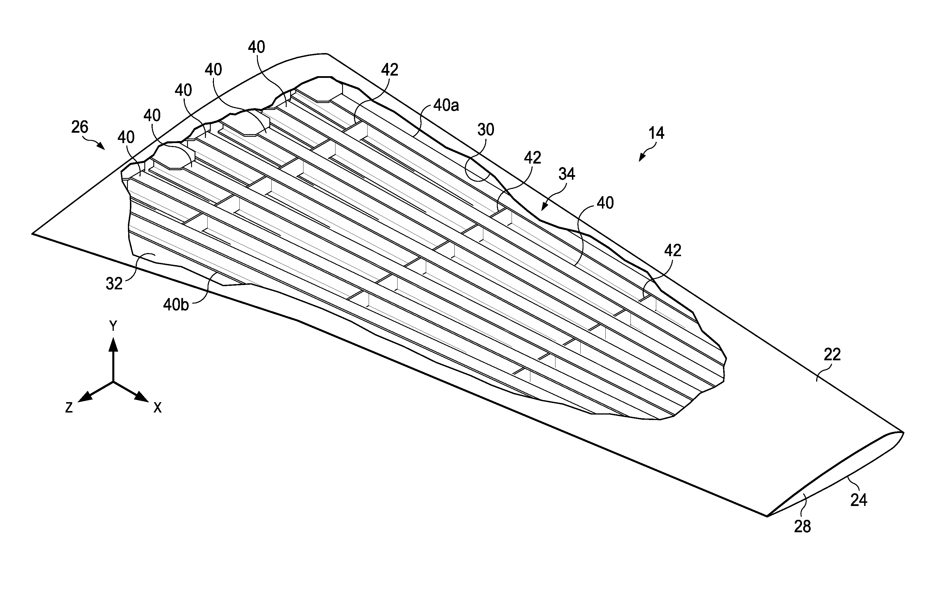
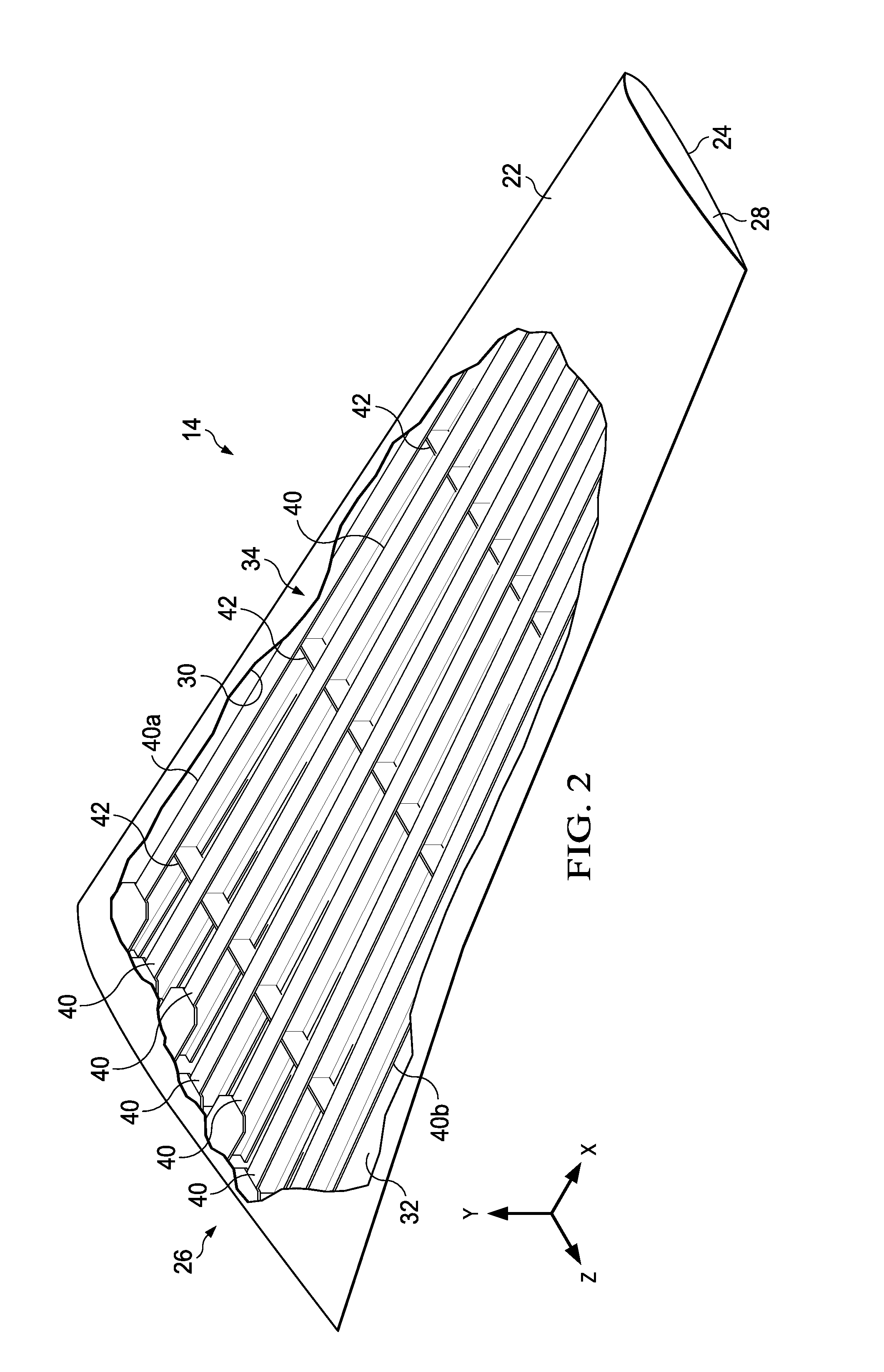
[0031]The embodiments of the aircraft wing structure described below utilize wing skin-grid differential features to improve wing-fuselage structural performance, and reduce manufacturing costs through lighter weight bonded designs. The disclosed wing structure may also reduce part count, may reduce or eliminate corrosion and may provide a higher structural margin of safety. The bonded aircraft wing structure exhibits increased wing design efficiency, is extremely light weight and provides fuel savings, while reducing or eliminates the need for fasteners to fasten the wing skins to the inner wing-grid and the spars. The wing structure has the ability to contain discrete damage, such as that caused by engine explosion.

[0032]In one exemplary embodiment, the bonded composite aircraft wing may include a composite inner wing-grid structure (hereinafter sometimes referred to as a wing-grid or wing-grid structure), and upper and lower composite wing skins that may be specifically tailored ...


PUM

PropertyMeasurementUnit
Angleaaaaaaaaaa
Fracture toughnessaaaaaaaaaa
Diameteraaaaaaaaaa

Abstract

A unitized composite aircraft wing includes upper and lower composite laminate wing skins that have differing stiffnesses and are bonded to a composite grid structure. The grid structure includes grid spars extending in a span-wise direction, and cross beams extending in a chord-wise direction of the wing. The grid spars include caps bonded to the upper and lower wing skins.

Description

BACKGROUND INFORMATION[0001]1. Field[0002]This disclosure generally relates to aircraft structures, and deals more particularly with a bonded composite wing.[0003]2. Background[0004]Fiber-reinforced resins, commonly referred to as “composites”, are being used more frequently in the aerospace structures because of their relatively high strength-to-weight ratios, good corrosion resistance, and other beneficial properties. Conventional composites used in aerospace applications include glass, carbon, or polyaramid fibers in woven and non-woven configurations, held in a resin matrix resin such as epoxy. Plies of the composite are laid up over tools and then cured through application of a combination of heat and pressure to form a hardened laminate. In some cases, a core material such as a foam or a honeycomb is placed between the plies to form a composite sandwich.[0005]In large commercial aircraft, composites are frequently employed in secondary structures but their use has been limited...

Claims


Application Information

Patent Timeline
IPC IPC(8): B64C3/20B64F5/00
CPCB64F5/0009B64C3/20B64C3/185B64C3/187B64C3/26Y02T50/40B29C70/88B64C3/18
Inventor DAN-JUMBO, EUGENE
Owner THE BOEING CO
Why Eureka
Try Eureka