Billiard cue

a cue ball and cue shaft technology, applied in the field of cues, can solve the problems of large and more undesirable deflection of the cue ball, and achieve the effects of reducing stiffness of the shaft, and reducing mass or weigh

Inactive Publication Date: 2008-10-07
CLAWSON CUSTOM CUES
View PDF31 Cites 12 Cited by
  • Summary
  • Abstract
  • Description
  • Claims
  • Application Information

AI Technical Summary

Benefits of technology

[0017]The present invention is a billiard cue which significantly reduces cue ball deflection by significantly reducing the mass and / or weight of the tip end of the shaft while maintaining the shaft stiffness substantially equal to or greater than the stiffness of a comparable shaft formed of solid maple.
[0020]In the latter aspect of the invention, the bore at the tip end of the shaft can be formed with a wall thickness of about 0.005 to about 0.050 inches. This reduces the weight of the tip end of the bore. However, the fiber / binder material forming the shaft, or at least at the tip end of the bore, has a significantly high stiffness to weight ratio to provide the requisite resistance to buckling on impact with a ball to reduce the deflection of the struck ball from its intended path of movement.
[0022]The billiard cue of the present invention is constructed to provide a significantly reduced mass or weight at the tip end of the shaft; while maintaining the stiffness of the shaft substantially equal to or greater than a conventional solid shaft made of hard maple. The reduced mass is achieved by forming a hollow bore in the shaft extending for a predetermined distance from the first end of the shaft thereby reducing the material weight at the first end of the shaft. This lower mass at the tip end of the shaft and high stiffness of the shaft material reduces flexure or buckling of the tip end of the cue shaft when the shaft impacts on a ball thereby significantly reducing the deflection of the struck ball from its intended path of movement generally parallel to the stroke axis of the cue shaft. However, the unique combination of stiffness and lightweight characteristics maintain the cue tip on the ball while allowing deflection of the tip as the ball begins to rotate.

Problems solved by technology

Experimentation by the Applicants has shown that a large amount of buckling results in a larger and more undesirable deflection of the cue ball from a path of movement parallel to the cue stroke line than when buckling is minimized and the end of the cue more easily flexes or bends outward from the center of the cue ball after impact with the cue ball.

Method used


Image

  • Billiard cue
  • Billiard cue
  • Billiard cue

Examples


Embodiment Construction

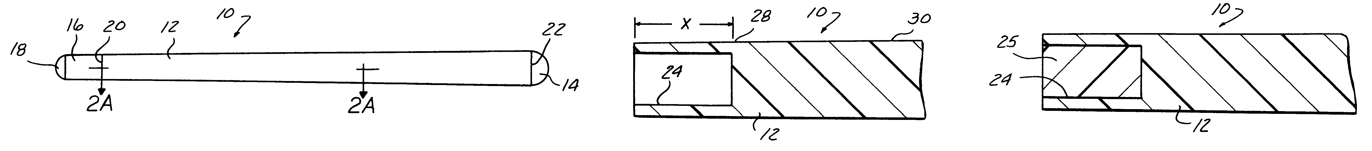
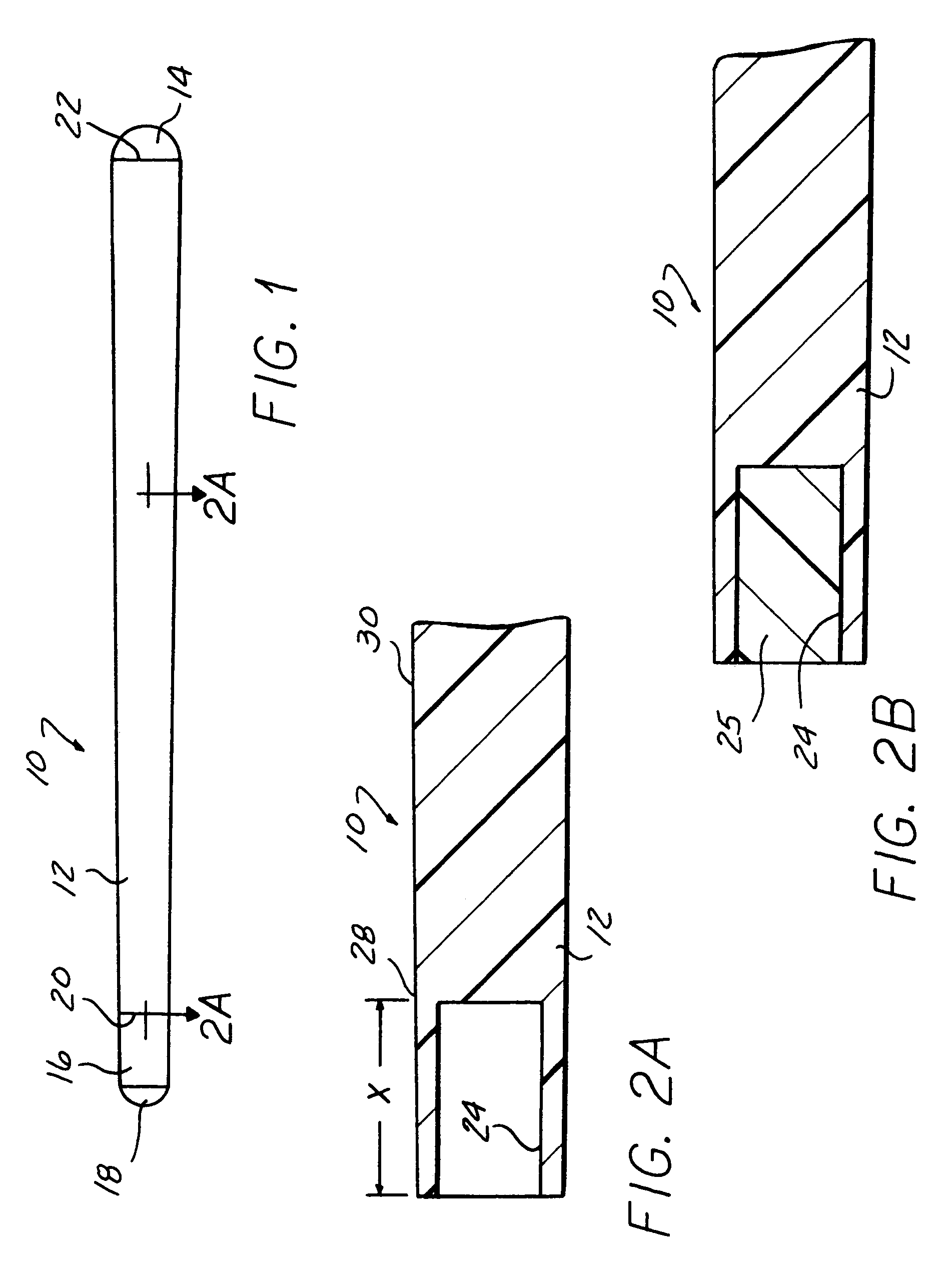
[0029]Referring now to the drawing, and to FIGS. 1 and 2A in particular, there is depicted a billiard / pool cue 10 constructed in accordance with the teachings of the present invention.

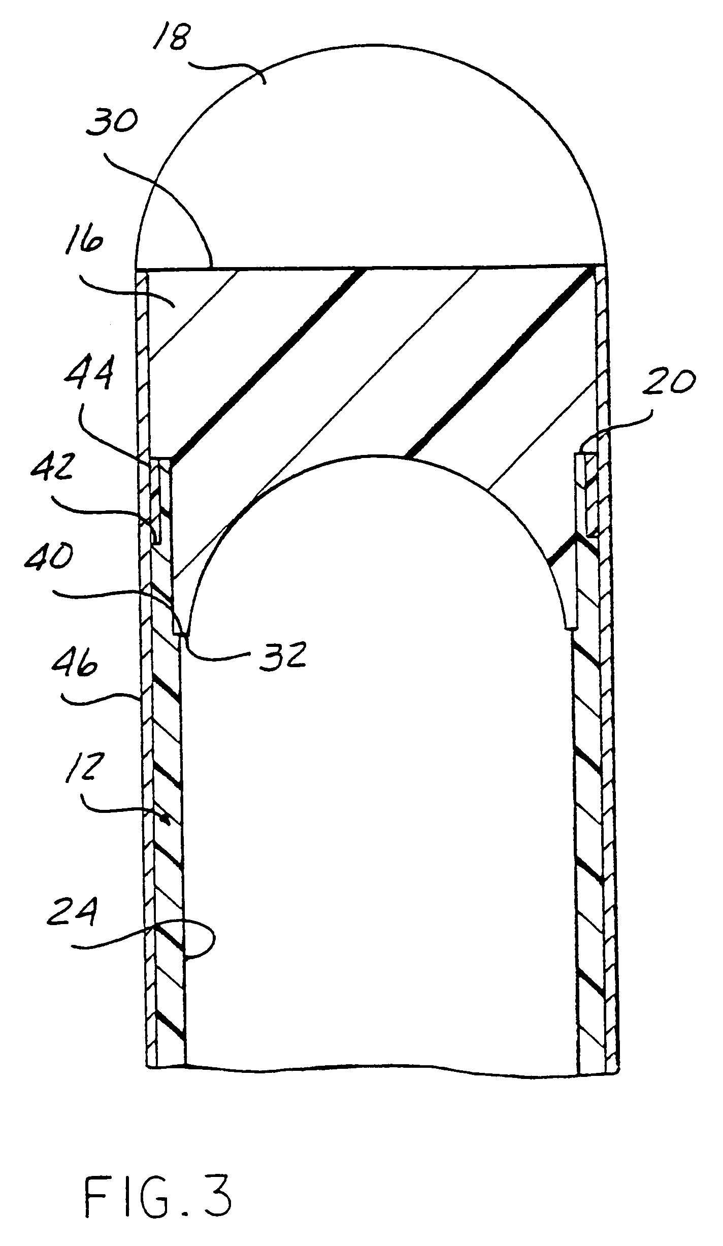
[0030]As shown in FIGS. 1-3, the cue 10 includes a shaft 12, a butt end 14, a ferrule 16 and a tip 18. The shaft 12 may be formed of a single elongated member or two short members which are coaxially joined together.

[0031]The shaft 12 has a first end 20 on which the ferrule 16 is mounted, as described hereinafter and an opposed second end 22 to which the butt 14 is mounted in a conventional manner. A bore 24 extends through the shaft 12 at least for a predetermined distance from the first end 20. Alternately, the bore 24 of the same or different diameter may extend for the entire length of the shaft 12 between the first and second ends 20 and 22. Although an exterior surface 26 of the shaft 12 may be formed with either American or European tapers, the inner diameter or I.D. of the bore 24 can remain co...


PUM

PropertyMeasurementUnit
thicknessaaaaaaaaaa
thicknessaaaaaaaaaa
diameteraaaaaaaaaa

Abstract

A billiard cue includes a shaft having a hollow bore extending for a predetermined distance from a first end of the shaft to reduce the tip end weight of the shaft. In one aspect, where the shaft is formed of a composite material consisting of fibers in a binder, such as carbon fibers in an epoxy resin, the bore forms an outer wall in the tip end of the shaft having a thickness between about 0.005 and about 0.05 inches The shaft material has a modulus of elasticity of at least 4.3×10⁶ psi. The bore extending from the first end of the shaft, the thin wall thickness of the tip end of the shaft and the material forming the shaft combine to decrease the mass of the tip end of the shaft while maintaining substantially all of the stiffness of a conventional solid wood shaft formed of a hard maple to minimize buckling of the tip end of the shaft and thereby substantially decrease deflection of the cue ball from its intended path of movement along a path parallel to the stroke axis of the shaft. The tip end bore may be left hollow or filled with a light weight, non-structural material. The hollow bore is equally applicable to shafts formed of wood.

Description

CROSS-REFERENCE TO CO-PENDING APPLICATION[0001]This application is a continuation of U.S. patent application Ser. No. 09 / 649,473, filed Aug. 28, 2000 now abandoned, the contents of which is incorporated herein by reference, which is a continuation-in-part of U.S. patent application Ser. No. 08 / 825,249, filed Mar. 27, 1997, now issued as U.S. Pat. No. 6,162,128, which is a continuation of U.S. application Ser. No. 08 / 314,864, filed Sep. 29, 1994, now U.S. Pat. No. 5,725,437, and a continuation-in-part of U.S. patent application Ser. No. 09 / 200,244 filed Nov. 25, 1998, now U.S. Pat. No. 6,110,051, which claims the benefit of the filing date of provisional application 60 / 066,589, filed Nov. 26, 1997.BACKGROUND[0002]1. Field of the Invention[0003]The present invention relates, in general, to billiard cues and, more specifically, to billiard cue shafts.[0004]2. Description of the Art[0005]Billiard or pool cues typically are formed of an elongated shaft; a butt at one end of the shaft and...

Claims


Application Information

Patent Timeline
Patent Type & Authority Patents(United States)
IPC IPC(8): A63D15/08A63D15/12
CPCA63D15/08A63D15/12
Inventor MCCARTY, ALLANTITUS, STEPHEN
Owner CLAWSON CUSTOM CUES
Why Eureka
Try Eureka