Pressure vessel vented boss with sintered metal plug

A technology for pressure vessels and sintered metals, applied in the direction of pressure vessels, vessel discharge methods, vessel filling methods, etc., capable of solving problems such as weakening the connection between the liner 20 and the boss 16

Active Publication Date: 2018-12-21
HEXAGON TECHNOLOGY AS
View PDF9 Cites 0 Cited by
  • Summary
  • Abstract
  • Description
  • Claims
  • Application Information

AI Technical Summary

Problems solved by technology

Additionally, gas trapped between the liner 20 and the shell 18 can migrate to the interface 62 between the liner 20 and the boss 16, thereby weakening the connection between the liner 20 and the boss 16.

Method used


Image

  • Pressure vessel vented boss with sintered metal plug
  • Pressure vessel vented boss with sintered metal plug
  • Pressure vessel vented boss with sintered metal plug

Examples


Embodiment Construction

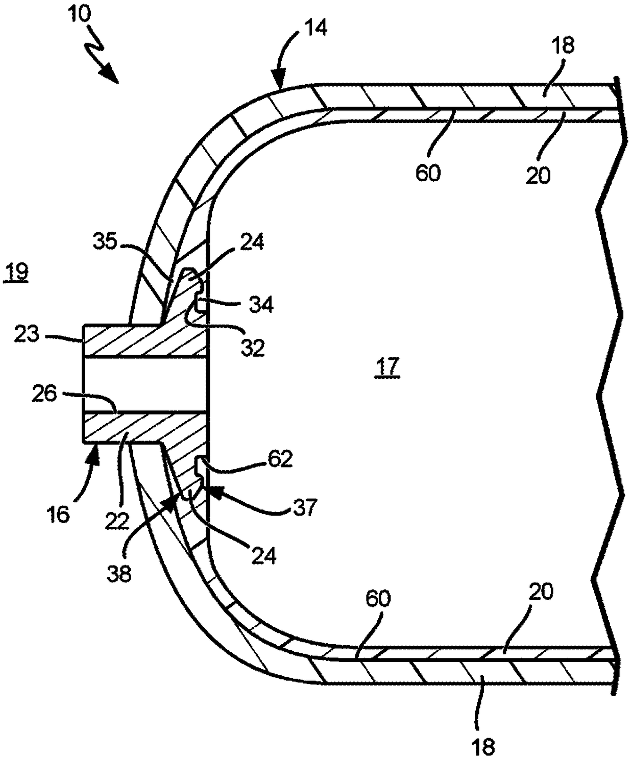
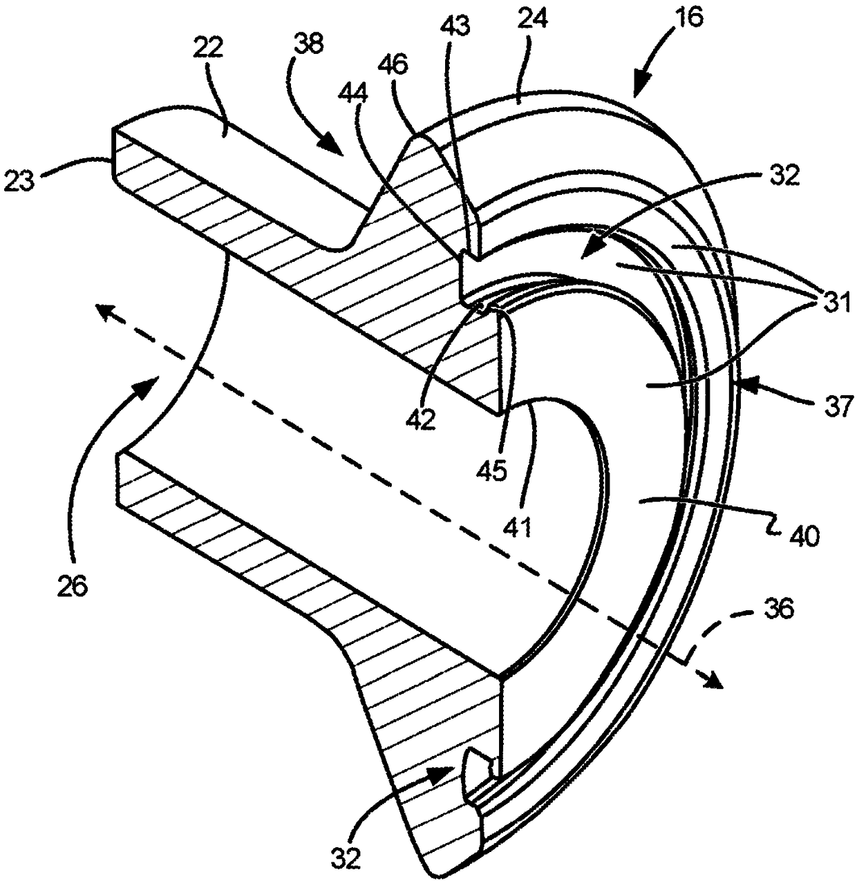
[0064] The present disclosure describes exemplary gas vent structures for use in pressure vessels and methods for producing such vent structures. The gas vent structure may be embedded in the boss of the pressure vessel such that the exemplary structure prevents separation of the liner from the boss and / or the liner from the shell under pressure. The gas vent structure allows gas trapped between the liner and the shell (or boss) to be vented, such as gas trapped between the liner and the interior surface of the shell that engages the liner. In one aspect, the present disclosure relates to combining at least one of the exemplary gas vent structures with the boss 16 of the pressure vessel 10 . In some embodiments, the vent structure is configured as a plug or insert positioned in a corresponding cavity of the boss. Each of the exemplary gas vent structures has features that allow gas accumulated between the liner 20 and the casing 18 (or boss 16 ) to vent to the internal enviro...


PUM

PropertyMeasurementUnit
densityaaaaaaaaaa
porosityaaaaaaaaaa

Abstract

A pressure vessel (10) includes a shell (18), a liner (20), and a boss (16). The liner (20) is positioned within the shell (18) and defines the interior environment (17). The boss (16) is located at afirst interface (60) between the shell (18) and the liner (20). The boss (16) includes a cavity (27) and a venting structure (28) located in the cavity (27). The cavity (27) is located at a second interface (62) between the liner (20) and the boss (16), and the cavity (27) is located at an interior surface (31) of the boss (16) in communication with the interior environment (17). A gas vent path(54) is defined from the first interface (60), through the venting structure (28), and into the interior environment (17) of the pressure vessel (10). The disclosure also describes a boss (16) for a pressure vessel (10) and a method of manufacturing the boss (16). The boss (16) includes a port (26), a flange (24), a cavity (27) and a gas venting structure (28). The cavity (27) and gas venting structure (28) are located on an interior (37) of the flange (24).

Description

Background technique [0001] Pressure vessels are commonly used to contain various fluids under pressure, such as, for example, hydrogen, oxygen, natural gas, nitrogen, propane, methane and other fuels. In general, pressure vessels can be of any size or configuration. The container may be heavy or light, disposable (e.g., disposable), reusable, high pressure (e.g., greater than 50 psi), low pressure (e.g., less than 50 psi), or, For example, for storing fluids at elevated or reduced temperatures. [0002] Suitable pressure vessel shell materials include metals, such as steel; or composite materials, which may include laminated layers of wound fiberglass filaments or other synthetic filaments bonded together by thermosetting or thermoplastic resins. The fibers can be glass fibers, aramid, carbon, graphite or any other commonly known fiber reinforcement. The resin material used may be epoxy, polyester, vinyl ester, thermoplastic, or any other suitable material that can provide...

Claims


Application Information

Patent Timeline
Patent Type & Authority Applications(China)
IPC IPC(8): F17C1/06F17C1/16
CPCF17C2201/056F17C2203/0619F17C2203/066F17C2221/011F17C2221/012F17C2221/014F17C2221/033F17C2221/035F17C2223/0123F17C2223/0153F17C2223/033F17C2223/035F17C2260/011F17C2260/037F17C1/06F17C1/16F17C2201/0109F17C2203/0604F17C2203/0663F17C2205/0305Y02E60/32B22F3/11B22F3/24F17C13/002B22F2998/10B22F2003/247F17C2205/0344F17C2260/036F17C2209/2181F17C2209/2163F17C2209/2109
Inventor 诺曼·L·纽豪斯查德·A·锡德伯格
Owner HEXAGON TECHNOLOGY AS
Why Eureka
Try Eureka