Multi-cavity tubes for air-over evaporative heat exchanger

A heat exchanger, evaporative technology, applied in the field of evaporative air heat exchanger, to achieve the effect of reducing the effective diameter, solving the increase of weight and cost, and improving the heat capacity

Pending Publication Date: 2018-12-21
EVAPCO
View PDF14 Cites 0 Cited by
  • Summary
  • Abstract
  • Description
  • Claims
  • Application Information

AI Technical Summary

Problems solved by technology

[0003] The present invention solves the problem of increasing weight and cost with incremental capacity increases by improving heat capacity while employing special tube shapes and patterns that increase the number of major surfaces in contact with the airflow to reduce cost for the same heat capacity , thus improving the heat capacity, while reducing the thickness of the heat exchange tube to reduce the cost of the same heat capacity

Method used


Image

  • Multi-cavity tubes for air-over evaporative heat exchanger
  • Multi-cavity tubes for air-over evaporative heat exchanger
  • Multi-cavity tubes for air-over evaporative heat exchanger

Examples


Embodiment Construction

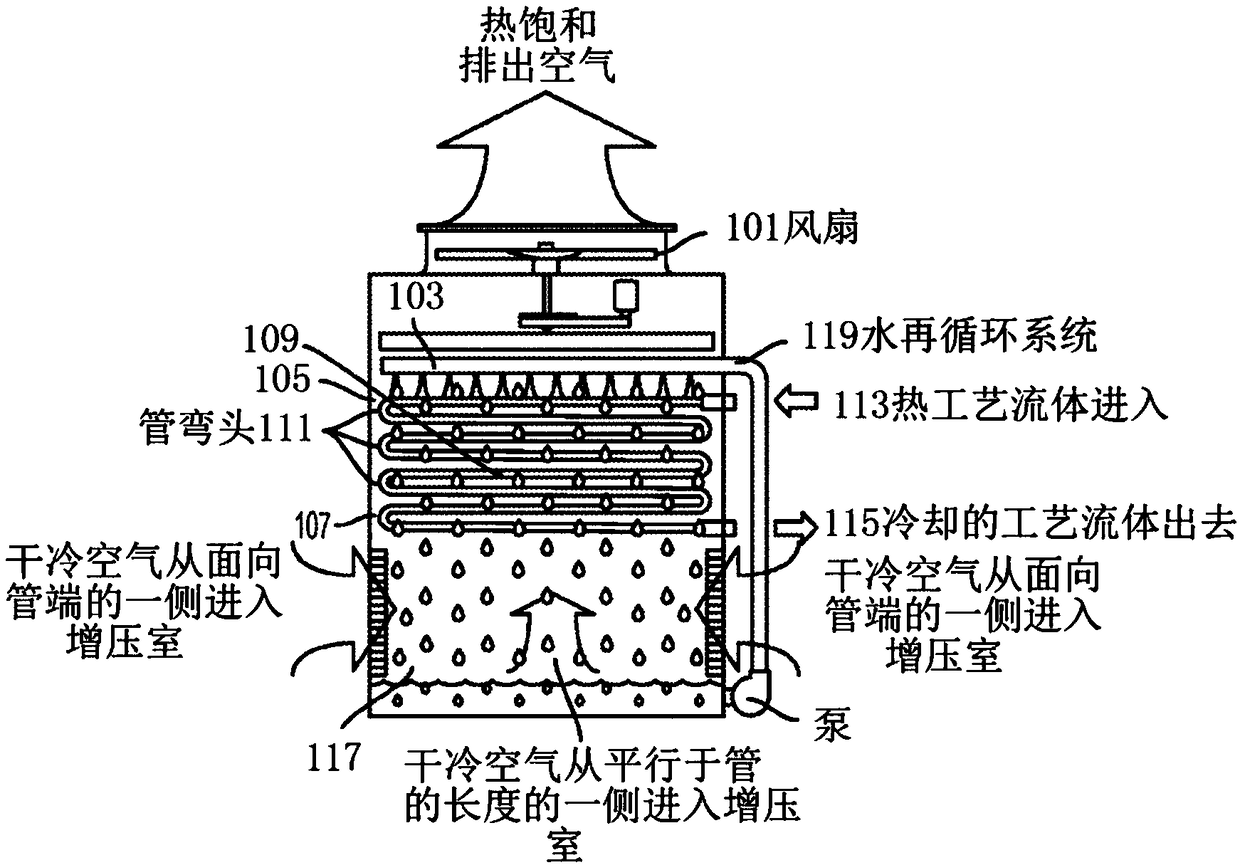
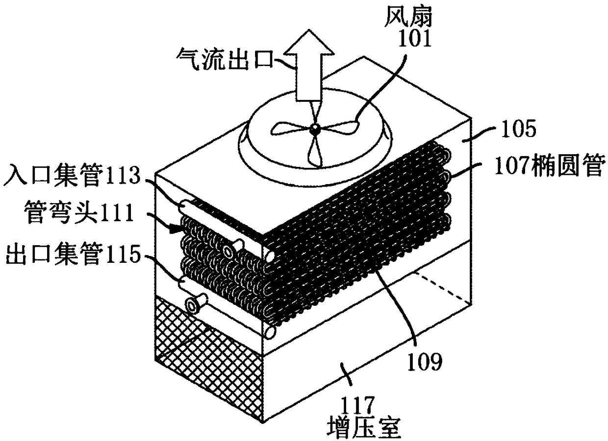
[0035] figure 1 and 2 An induced draft single cell evaporative cooler according to the prior art is shown. The fan 101 draws air into the device and forces it out the top of the device. Below the fan is the water distribution system 103 which distributes water over the coil 105 . The coil consists of a row of serpentine oval tubes 107 . Each length of tube 109 is connected at its end to an adjacent higher and / or lower length of tube by a tube bend 111 . Process fluid to be cooled enters the tubes through inlet header 113 and leaves the tubes through outlet header 115 . Below the coil is a plenum 117 where air enters the unit and water delivered to the unit by the water distribution system 103 is cooled by direct heat exchange with the air, water is collected at the bottom and recirculated to the top by a water recirculation system 119 .

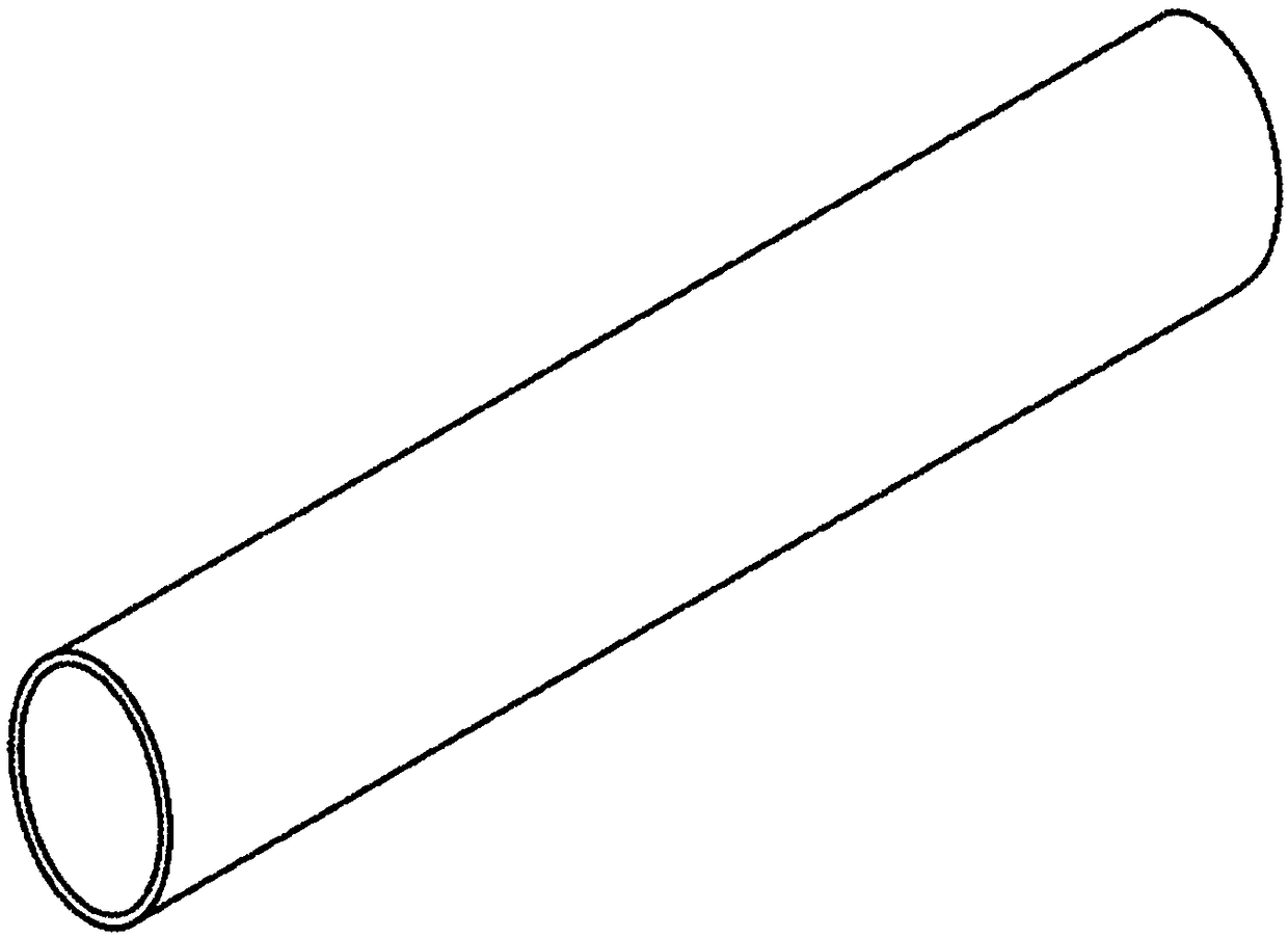
[0036] image 3 and 4 show figure 1 and 2 A conventional evaporative heat exchanger oval tube 107 used in prior art heat exchangers...


PUM


Abstract

An air-over evaporative heat exchanger with multi-lobed or peanut-shaped tubes replacing conventional round or elliptical tubes. The tubes have a narrow horizontal cross section and tall vertical cross section to allow the multiplication of surface area in the same coil volume while maintaining or increasing the open-air passage area. The configuration allows the coil to have an overall external heat transfer coefficient much higher than a conventional coil, while the tube shape allows the use of thinner material, reducing the weight and cost of the heat exchanger.

Description

technical field [0001] This invention relates to evaporative air heat exchangers. Background technique [0002] As we all know, oval tubes are suitable for evaporative heat exchangers. Increasing the heat exchanger tube density is effective for systems with no airflow over the coils, while increasing the external surface area with extended fins is effective for systems with airflow over the coils. However, these methods increase the weight of the heat exchanger coils and thus the cost per heat exchanger compared to conventional tube-coil designs, since the tubes need to have a minimum wall thickness to operate at internal pressure. Will not deform. Contents of the invention [0003] The present invention solves the problem of increasing weight and cost with incremental capacity increases by improving heat capacity while employing special tube shapes and patterns that increase the number of major surfaces in contact with the airflow to reduce cost for the same heat capaci...

Claims


Application Information

Patent Timeline
Patent Type & Authority Applications(China)
IPC IPC(8): F28F1/00F28F1/02F28F1/06F25B39/00F25B39/02F28D5/00F28D5/02
CPCF28C1/14F28D1/0478F28F1/02F28F1/06F28D2021/0063Y02B30/70F28D3/02F28D3/04F28D15/00F28F2025/005
Inventor J·凯恩D·J·瓦迪尔
Owner EVAPCO
Why Eureka
Try Eureka