
Busbar current sensor assembly

A technology of sensor components and current sensors, which is applied in the direction of electrical components, current only, voltage/current isolation, etc., and can solve problems such as reducing the magnetic field

Active Publication Date: 2018-12-21
SAFRAN ELECTRICAL & POWER
View PDF7 Cites 2 Cited by
  • Summary
  • Abstract
  • Description
  • Claims
  • Application Information

AI Technical Summary

Problems solved by technology

Alternatively, the current sensor can be placed on the opposite side of the conductor, but a hole must be formed in the conductor and the sensor must be placed precisely near the hole to reduce the magnetic field for proper measurement
However, these methods have various disadvantages and need to be improved

Method used


Image

  • Busbar current sensor assembly
  • Busbar current sensor assembly
  • Busbar current sensor assembly

Examples


Embodiment Construction

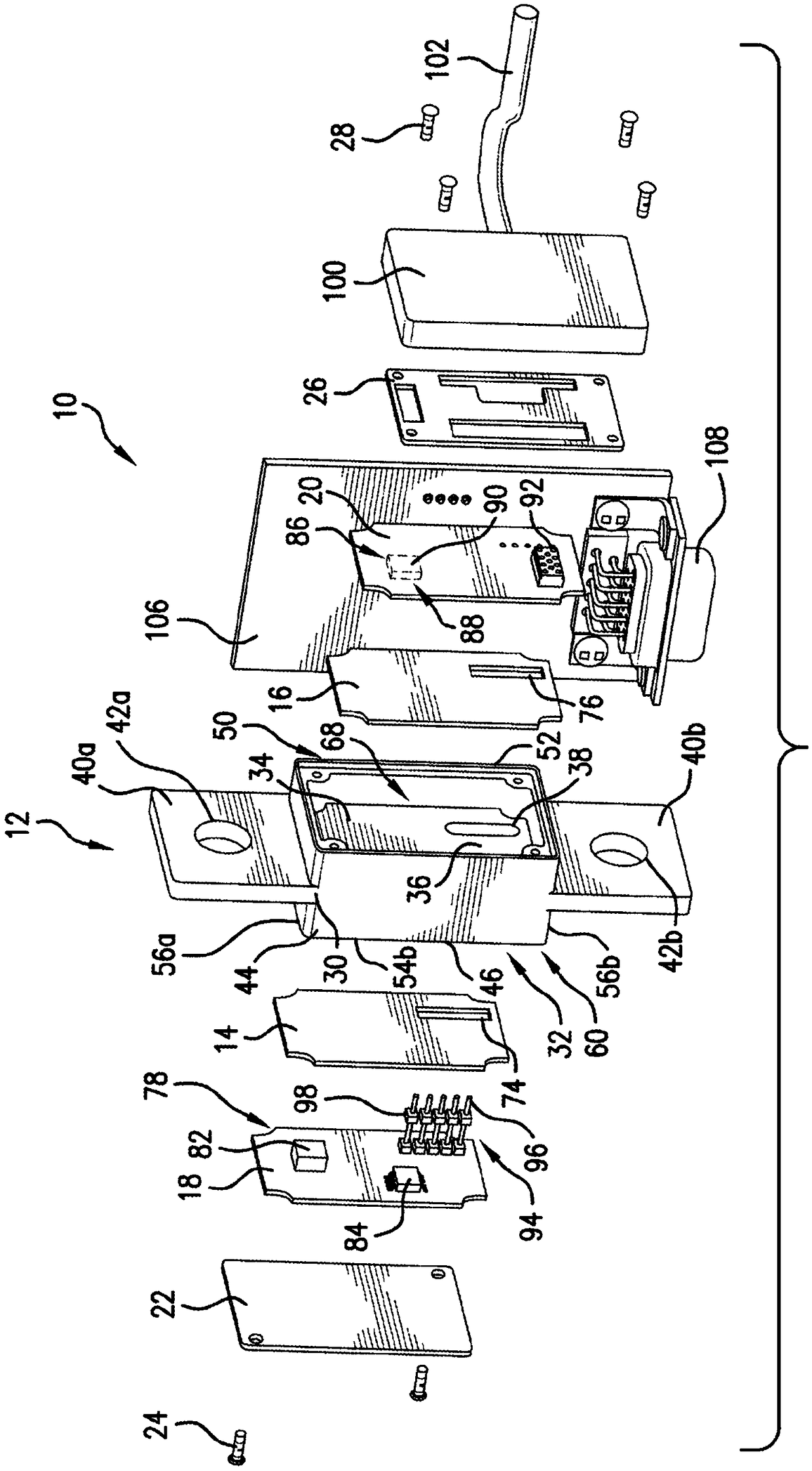
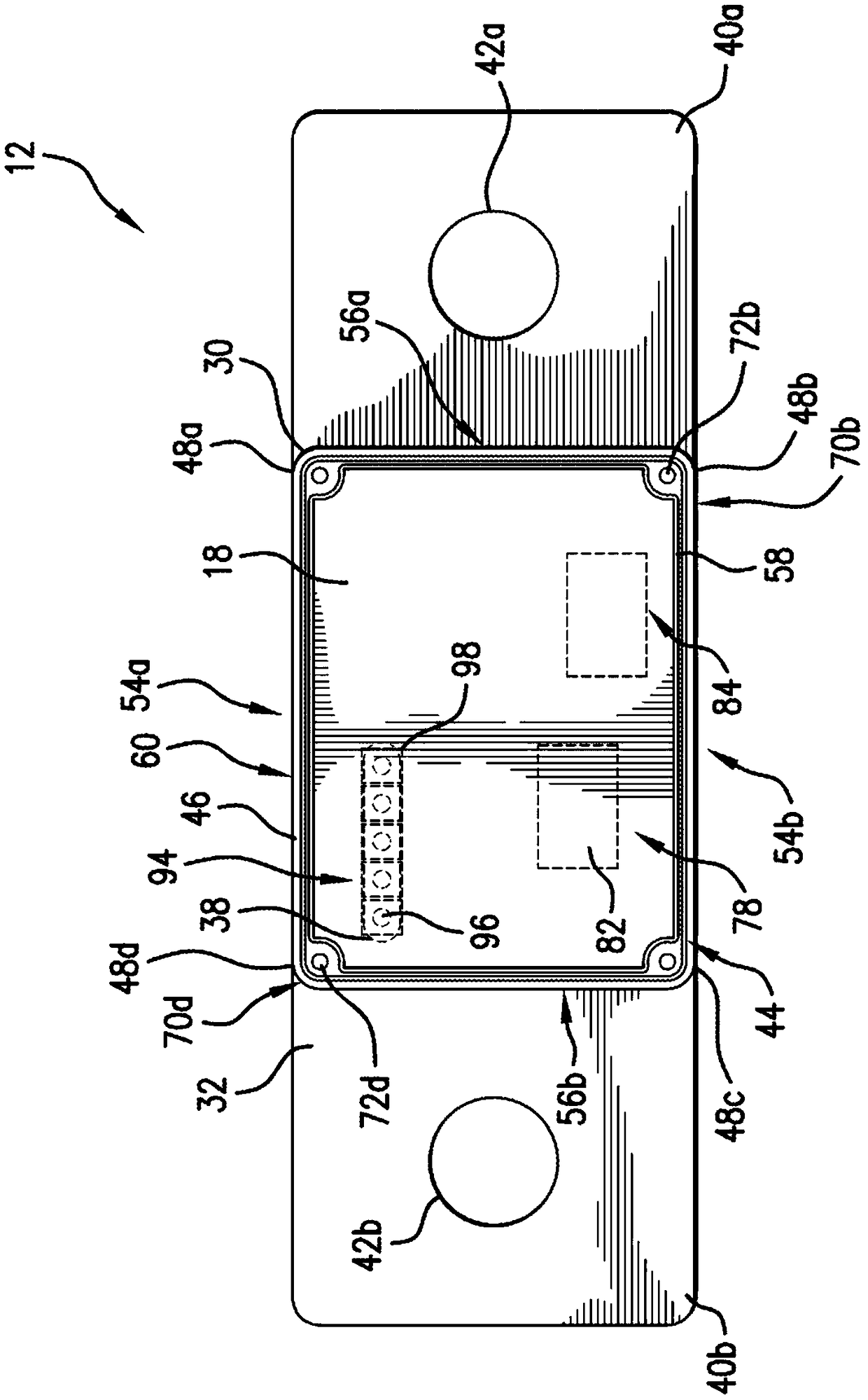
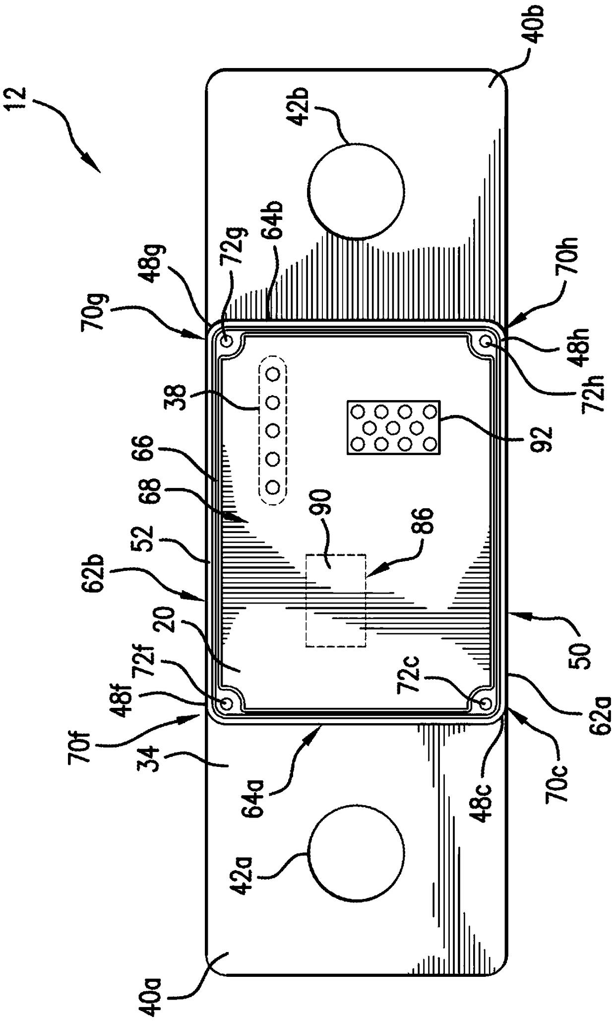
[0010] figure 1 Components of bus current sensor assembly 10 are depicted. The bus bar current sensor assembly 10 may include a bus bar member 12, a first insulator 14, a second insulator 16, a first circuit board 18, a second circuit board 20, a first cover 22, a first fastener 24, a second cover 26 and Second fastener 28 .

[0011] refer to Figure 1-3 , the bus bar member 12 is made of conductive material, such as copper or aluminum. Also, the busbar member 12 may be coated with any number of substances including, for example, nickel. The busbar member 12 includes a base 30 having a first surface 32 facing in a first direction and a second surface 34 facing in a second direction. The first direction is opposite to the second direction. A cross-section of the busbar member 12 can be manipulated to adjust the magnetic field strength in the vicinity of the magnetic field sensing components. It will be appreciated, however, that there are practical limitations to adjustin...


PUM


Abstract

A busbar current sensor assembly (10) includes a busbar member (12) that includes a first cavity (60) and a second cavity (68). The second cavity is disposed opposite the first cavity. The busbar current sensor assembly also includes a first current sensor (78) disposed in the first cavity such that the first cavity at least partially surrounds the first current sensor and a second current sensor(86) disposed in the second cavity such that the second cavity at least partially surrounds the second current sensor.

Description

technical field Background technique [0001] In the aerospace power distribution industry, distribution boxes may include integral current sensing capabilities. Current sensors are often used to detect excessive fault currents so that aircraft power distribution systems can quickly change operating modes to prevent damage and enable sustainable and safe aircraft operation. [0002] When current is passed through a wire, cable or busbar (hereinafter referred to as "conductor"), a magnetic field is generated around the conductor. The magnitude of the magnetic field is linearly related to the magnitude of the current. Therefore, by detecting the magnitude of the magnetic field, the magnitude of the current can be determined. [0003] There are various methods of measuring the magnetic field to determine the current. Preferably, the magnetic field / current sensor is matched to the magnitude of the magnetic field generated by the flowing current to be measured. This can be done...

Claims


Application Information

Patent Timeline
IPC IPC(8): G01R15/20G01R1/04G01R19/00
CPCG01R1/04G01R15/202G01R19/0092G01R15/20G01R17/16H01R25/165
Inventor 凯文·弗朗西斯·汉利托马斯·斯奈德
Owner SAFRAN ELECTRICAL & POWER
Learn More