Eureka AIR delivers breakthrough ideas for toughest innovation challenges, trusted by R&D personnel around the world.

Digital closed loop type optical fiber current sensor

A fiber-optic current and digital closed-loop technology, applied in voltage/current isolation, measuring current/voltage, instruments, etc., can solve problems such as long lag time, difficulty in improving response speed, slow response speed, etc., and achieve the effect of improving sensitivity

Active Publication Date: 2011-01-26
CHINA ELECTRIC POWER RES INST +1
View PDF11 Cites 36 Cited by
  • Summary
  • Abstract
  • Description
  • Claims
  • Application Information

AI Technical Summary

Problems solved by technology

For this reason, in addition to a series of calculations necessary for digital closed-loop such as square wave amplitude detection, feedback ladder slope generation, and feedback gain correction on the basis of such an input signal, this fiber optic current sensor has to perform a large number of derating. Noise operation, and the noise reduction result of a certain point data is related to a large amount of data before and after this point (in theory, it should be related to the global data), so the lag time of the method itself (not the calculation time related to the operating speed of the device) is long, resulting in response The speed is slow, so the latest US patent "Optical sensor, optical current sensor and optical voltage sensor" (application number: 20090212763) lists "It is difficult to improve response speed..." as this fiber optic current sensor one of the problems

Method used


Image

  • Digital closed loop type optical fiber current sensor
  • Digital closed loop type optical fiber current sensor
  • Digital closed loop type optical fiber current sensor

Examples


Embodiment Construction

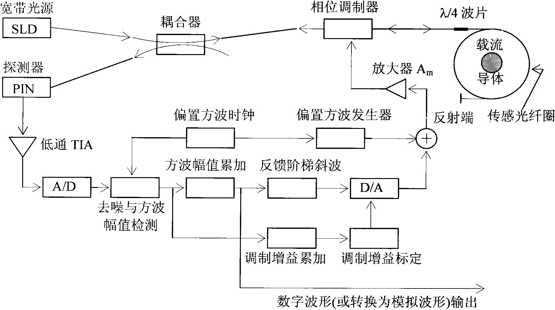
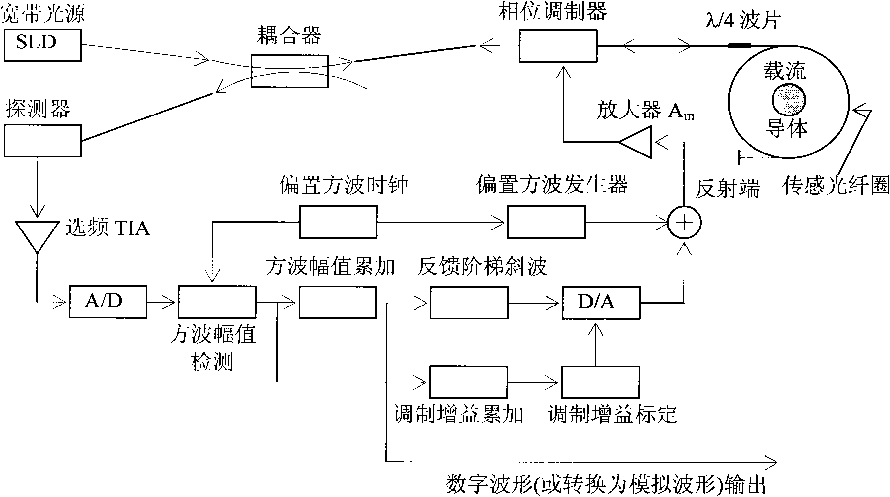
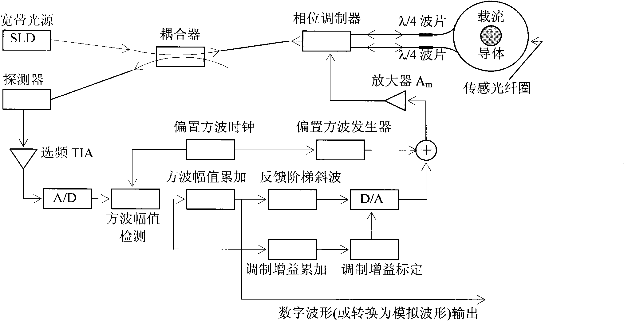
[0078] In order to improve the dynamic range and response speed of the digital closed-loop fiber optic current sensor, we can start by reducing the noise level of the output signal of the preamplifier of the signal processing system, because this can not only improve the measurement accuracy of the small signal end, but also reduce the lag of signal processing time. The solution proposed in this patent application is: the light wave phase modulation adopts a square wave, and the signal processing is no longer based on a square wave, but on a sine wave (hereinafter referred to as the square wave-sine wave solution). In order to explain why such a scheme can achieve this goal, we first analyze the signal characteristics that the digital closed-loop fiber optic current sensor needs to process.

[0079] by figure 1 The optical path and circuit simplified diagram (referring to U.S. Patent No. 5,914,781, etc.) of the existing reflective square wave modulation-square wave detection ...


PUM


Abstract

The invention provides a digital closed loop type optical fiber current sensor. A modulation signal of a light wave phase modulator of a sensor optical path system is an amplitude modulation square wave; a signal processing system extracts any harmonic wave of amplitude modulation square wave current output by a photoelectric transducer and extracts tested current information from the current; a pre-amplifier of the signal processing system is a transimpedance amplifier TIA, and the bandwidth is below 1 / 650 when the square wave transient amplitude value (prior art) is directly extracted from the amplitude modulation square wave, so that thermal noise output by the pre-amplifier and the shot noise level are also reduced to be below 1 / 650 of the prior art; and current-voltage conversion gain of the transimpedance amplifier TIA is not determined by the resistance of a feedback network of the TIA, so that a low-resistance resistor is adopted in the feedback network of the TIA while the high current-voltage conversion gain is ensured, and the thermal noise of the resistor which accounts for a significant proportion in the level of the noise output by the TIA is reduced to be negligible.

Description

technical field [0001] The invention belongs to the field of sensitive electronics and sensors in electronics and information systems, and the field of high-voltage and high-current measurement in electrical engineering, and specifically relates to a digital closed-loop optical fiber current sensor. The present invention is also applicable to digital closed-loop optical fiber gyroscopes and various digital closed-loop optical fiber interferometers including digital closed-loop optical fiber Sagnac interferometers, especially those with weak light intensity corresponding to the extracted signal in the optical signal output by the optical path The aforementioned sensors, gyroscopes, interferometers. Background technique [0002] With the development of power systems, new technologies based on power electronics such as DC transmission technology, flexible AC transmission technology, and digital substations are more and more widely used in power systems. Power systems are very i...

Claims


Application Information

Patent Timeline
Patent Type & Authority Applications(China)
IPC IPC(8): G01R19/00G01R15/24G02B27/28
CPCG01R15/247G01R15/246
Inventor 陈祥训陈硕尹树杰刘占元
Owner CHINA ELECTRIC POWER RES INST
Why Eureka
Eureka Blog
Learn More