
Non-isolated power supply output chassis ground fault detection and protection system

a protection system and power supply technology, applied in power conversion systems, dc-dc conversion, apparatus without intermediate ac conversion, etc., can solve problems such as power supply damage, power supply potential damage, and insufficient use of techniques, so as to prevent damage to semiconductor switches and/or other components of power supply

Active Publication Date: 2016-04-28
HONEYWELL INT INC
View PDF1 Cites 31 Cited by
  • Summary
  • Abstract
  • Description
  • Claims
  • Application Information

AI Technical Summary

Benefits of technology

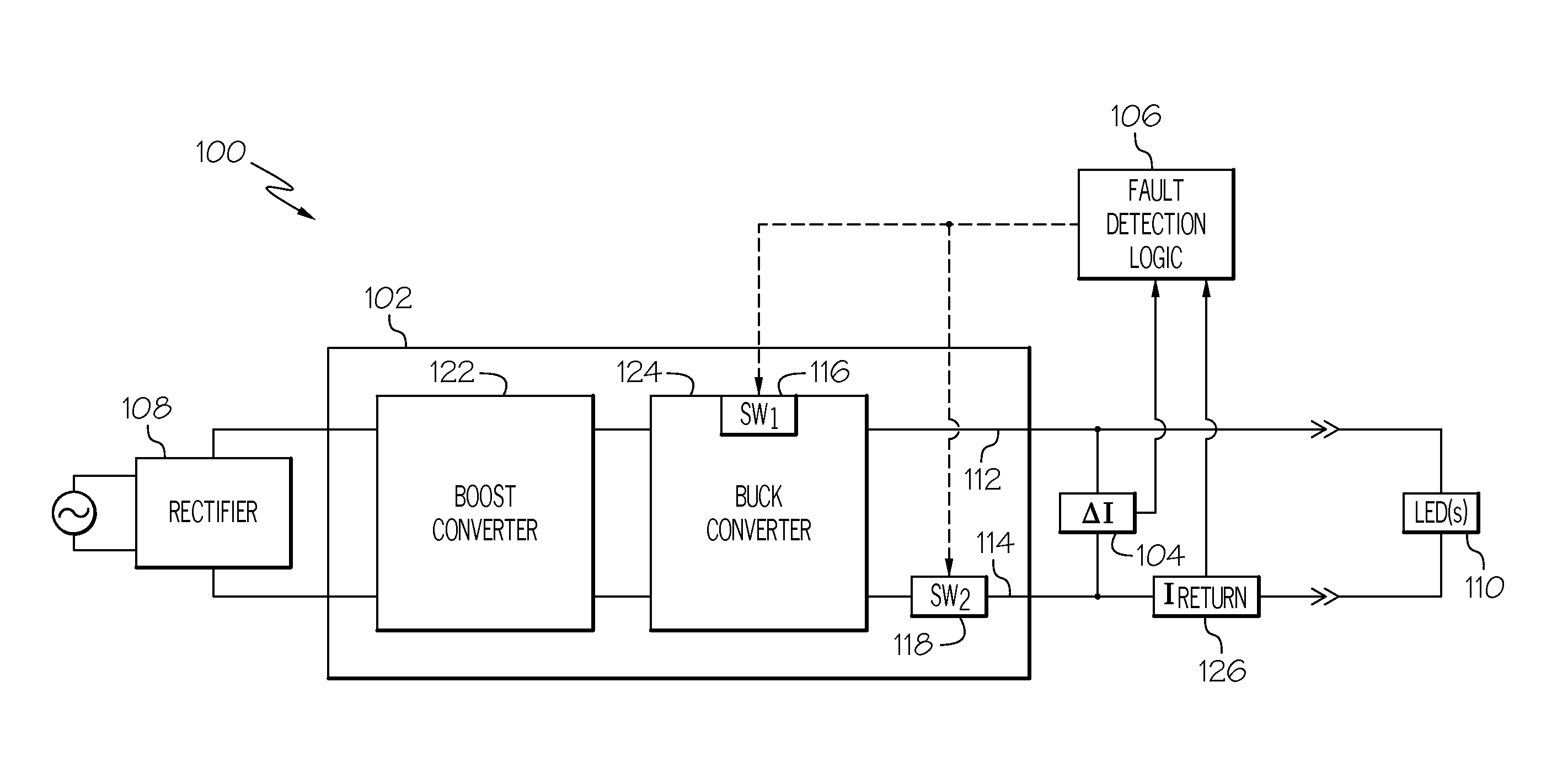
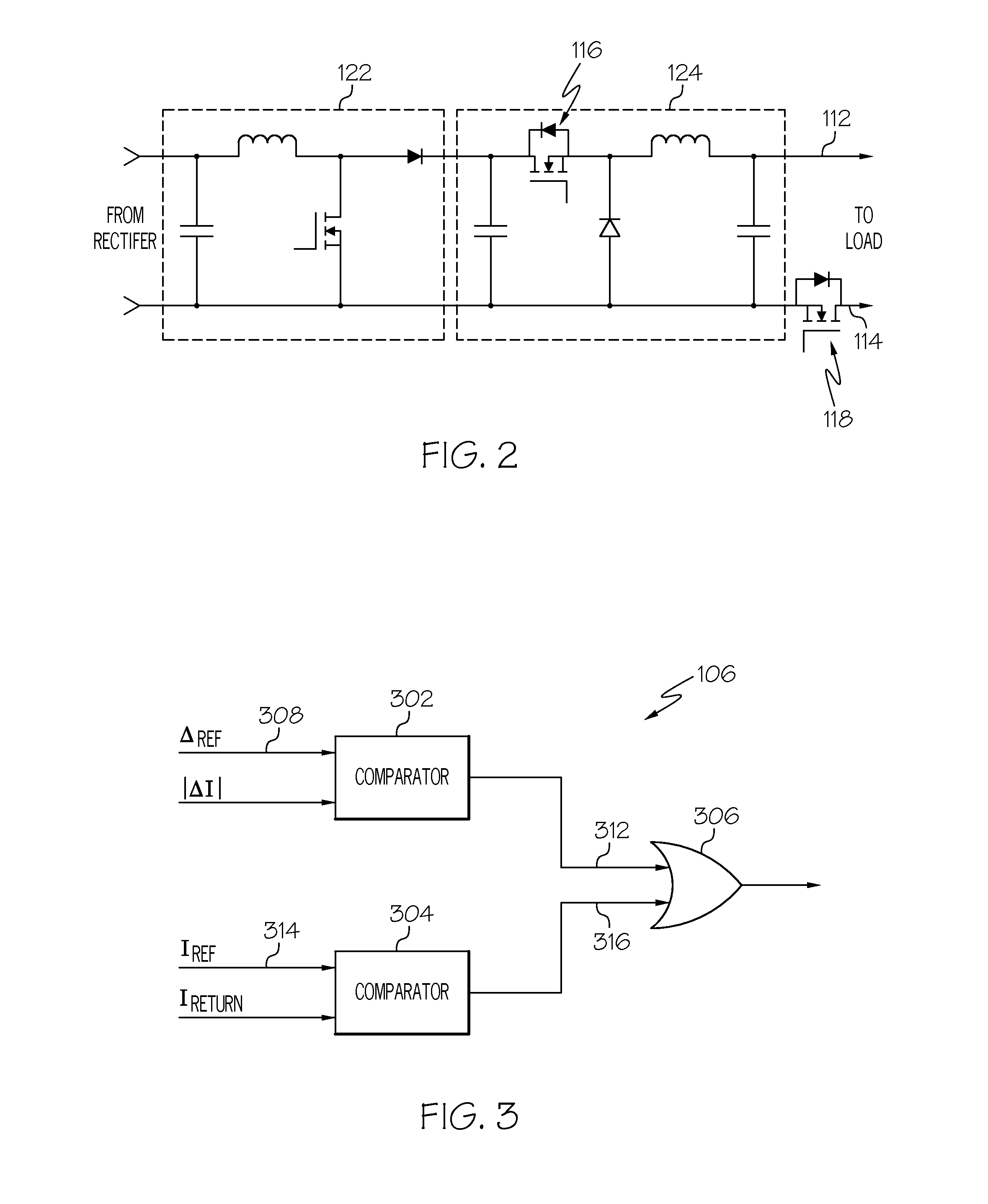
The patent describes a circuit that includes a non-isolated power supply, a differential current sensor, and fault detection logic. The non-isolated power supply is a DC-DC converter that receives an input voltage and supplies an output voltage. The differential current sensor senses the difference in current between the supply and return lines. The fault detection logic is coupled to the differential current sensor, the return line current sensor, the first semiconductor switch, and the second semiconductor switch. When the differential current exceeds a predetermined threshold, the logic will command the semiconductor switches to operate in the off state to protect the circuit. The technical effect of this patent is to provide a circuit with improved protection against overcurrent events and to enhance the safety and reliability of the circuit.

Problems solved by technology

However, one downside of this topology is that the output voltage needs to be higher than the AC source peak voltage, thus necessitating, in most applications, another DC-DC converter, a buck converter, in order to reduce the voltage level used to drive the LEDs.
Adding isolation in the downstream DC-DC converter is possible but it negatively impacts overall system efficiency, size, and weight.
Thus, in the unlikely event the LED side of the above-described non-isolated power supply was to become shorted to chassis, the source finds a low impedance path through the short and the controller goes out of bounds, resulting in the power supply potentially being damaged.
The presently used techniques are not sufficiently fast, and will not be able to protect against the ground fault condition, even with existing differential current monitoring and protection techniques, thus potentially damaging the power supply.

Method used


Image

  • Non-isolated power supply output chassis ground fault detection and protection system
  • Non-isolated power supply output chassis ground fault detection and protection system
  • Non-isolated power supply output chassis ground fault detection and protection system

Examples


Embodiment Construction

[0016]The following detailed description is merely exemplary in nature and is not intended to limit the invention or the application and uses of the invention. As used herein, the word “exemplary” means “serving as an example, instance, or illustration.” Thus, any embodiment described herein as “exemplary” is not necessarily to be construed as preferred or advantageous over other embodiments. All of the embodiments described herein are exemplary embodiments provided to enable persons skilled in the art to make or use the invention and not to limit the scope of the invention which is defined by the claims. Furthermore, there is no intention to be bound by any expressed or implied theory presented in the preceding technical field, background, brief summary, or the following detailed description.

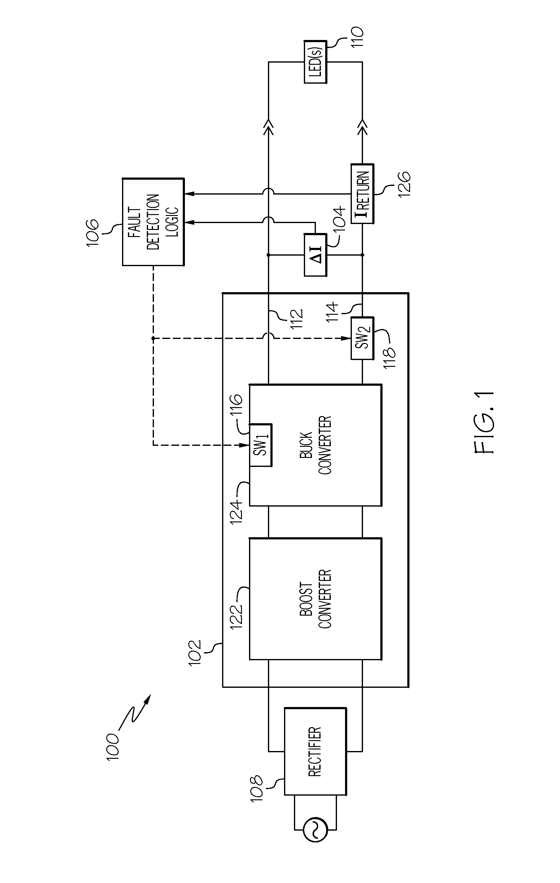
[0017]Referring now to FIG. 1, a functional block diagram of one embodiment of a circuit. The depicted circuit includes a non-isolated power supply and a system for detecting and protecting the...


PUM


Abstract

A non-isolated power supply is configured to receive an input voltage and supply an output voltage, and includes a supply line, a return line, a first semiconductor switch coupled in series in the supply line, and a second semiconductor switch coupled in series in the return line. The first and second semiconductor switches are each configured to operate in an ON state and an OFF state. The differential current sensor is configured to sense differential current between the supply line and the return line. The fault detection logic is coupled to the differential current sensor, the first semiconductor switch, and the second semiconductor switch, and is configured to detect when the differential current exceeds a predetermined current magnitude, and command the first and second semiconductor switches to operate in the OFF state upon detecting that the differential current exceeds the predetermined current magnitude.

Description

TECHNICAL FIELD[0001]The present invention generally relates to non-isolated power supplies, and more particularly relates to a system for detection and protection of chassis ground faults in non-isolated power supply topologies.BACKGROUND[0002]In recent years, various industrial and technology sectors, including aerospace, industrial, medical, and municipal, are turning to LED based lighting systems as alternatives to existing lighting solutions. This is due, at least in part, to the fact that LEDs can offer very high luminous intensity, which can be controlled over a wide range with suitable power conversion and driver circuit. Moreover, LEDs are relatively small and relatively more reliable.[0003]Many power supply topologies may be used to drive and control the luminous intensity of LEDs. A vast majority of the proposed topologies are powered from an AC source, and thus rely on a power factor corrected (PFC) AC-DC converter at the front end. One common PFC AC-DC converter topolog...

Claims


Application Information

Patent Timeline
IPC IPC(8): H02H3/08H02M3/04
CPCH02M3/04H02H3/08H02H7/1213H02M1/32H02M3/1582H05B47/26
Inventor SAXENA, SUNIT KUMARMAHAJAN, DEEPAK BHIMRAOSAHA, TARAKRAVI, ANAND VIVEK
Owner HONEYWELL INT INC
Learn More