Current Transducer For Measuring An Electrical Current

a current transducer and current technology, applied in the direction of short-circuit testing, magnetic measurements, instruments, etc., can solve the problems of machine damage, short-circuit testing, and limited accuracy of clamp-on ammeters, and achieve high immunity

Inactive Publication Date: 2014-01-09
SENIS
View PDF13 Cites 34 Cited by
  • Summary
  • Abstract
  • Description
  • Claims
  • Application Information

AI Technical Summary

Benefits of technology

[0011]with high immunity to disturbing magnetic fields, particularly those produced by other current-carrying cables,

Problems solved by technology

The accuracy of a clamp-on ammeter is also limited by the dependence of the measurement result on the position of the enclosed cable with respect to the symmetry axis of the ferromagnetic core.
Big electrical machines of all kinds and for different purposes, like for example electricity generators, may develop during manufacture or in the course of time a current leakage path which may result in the worst case in a short circuit.
There is a high risk that the machine is damaged if a short circuit occurs.

Method used


Image

  • Current Transducer For Measuring An Electrical Current
  • Current Transducer For Measuring An Electrical Current
  • Current Transducer For Measuring An Electrical Current

Examples


first embodiment

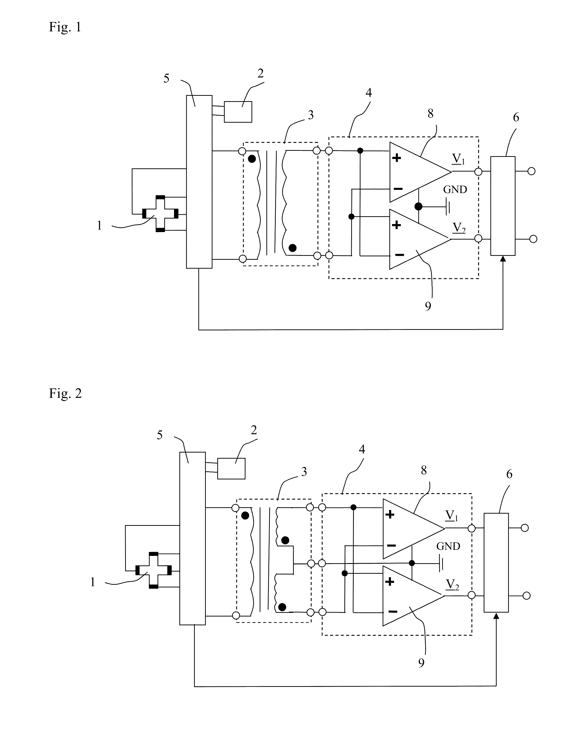
[0076]FIG. 2 shows a first variant of the first embodiment where the transformer 3 has a secondary winding with three output terminals, one of the output terminals being a middle terminal. The middle terminal is coupled to ground GND, either directly or as shown to a ground terminal GND of the preamplifier 4.

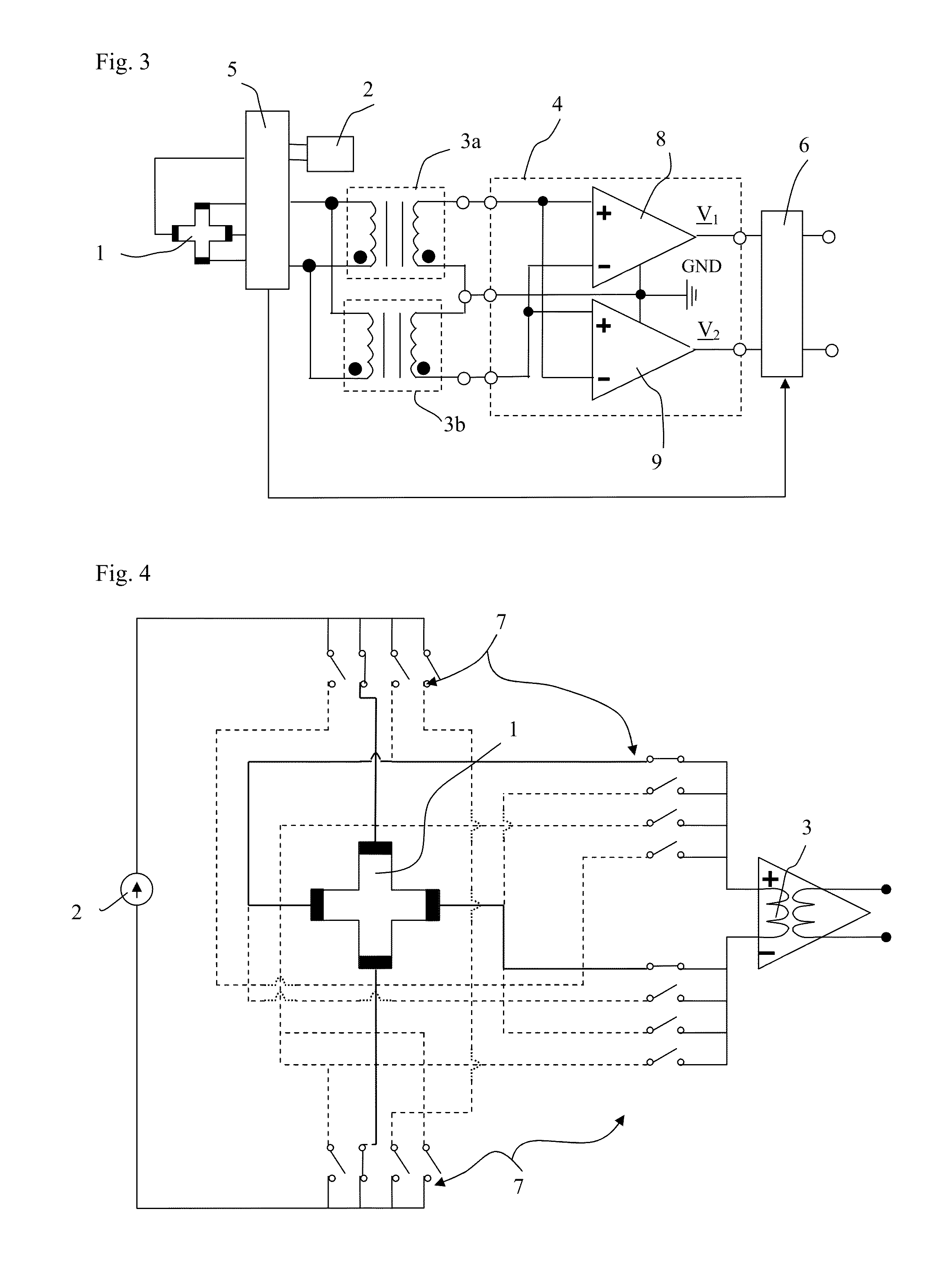
[0077]FIG. 3 shows a second variant of the first embodiment where the transformer 3 is composed of two transformers 3a and 3b. The primary windings of the two transformers 3a and 3b are coupled in a parallel manner, the secondary windings are coupled such that two of the four output terminals of the transformers 3a and 3b form a middle terminal. The middle terminal is coupled to ground GND, either directly or as shown to a ground terminal GND of the preamplifier 4.

[0078]In all these embodiments the Hall element 1 is operated according to the spinning current method and it is the logic block 5 that serves for this purpose. The spinning current method consists in coupling the Hall...

fifth embodiment

[0089]Instead of the Hall element(s) or AMR sensor(s), the magnetic transducer may also comprise any other type of magnetoresistive sensors, like e.g. GMR (giant magnetoresistive sensor) sensor(s), or one or more fluxgate sensors. A fluxgate sensor consists of a small, magnetically susceptible core wrapped by two coils of wire. A current source provides an alternating electrical current having a predetermined frequency which is passed through the first coil, driving the core through an alternating cycle of magnetic saturation; i.e., magnetised, unmagnetised, inversely magnetised, unmagnetised, magnetised, and so forth. This constantly changing magnetization induces an electrical voltage in the second coil, the phase of which depends on the external magnetic field to be measured. FIG. 15 shows a diagram of a magnetic transducer according to the invention. In this embodiment, the magnetic transducer comprises two fluxgate sensors 32 and 33. The first coil of the fluxgate sensor 32 is ...

sixth embodiment

[0090]FIG. 16 shows a diagram of a magnetic transducer according to the invention. In this embodiment, the magnetic field sensors are AMR sensors. The AMR sensor 19 is coupled to a first amplification chain comprising the same components as in the previous embodiments and labelled with the literal “a”, the AMR sensor 31 is coupled to a second amplification chain comprising the same components as in the previous embodiments and labelled with the literal “b”. The outputs of the phase sensitive detectors 6a and 6b are coupled to a voltmeter 34 or to an analog to digital converter. However, the transformers may be configured as in any of the previous embodiments. The magnetic field sensors could also be Hall elements or fluxgate sensors in which cases the logic block 5a would have to be modified for Hall elements or fluxgate sensors as shown above.

[0091]In all embodiments with two sensors of any kind, it is preferred to have one transformer having one single magnetic core, two primary w...


PUM


Abstract

The invention concerns a current transducer for measuring a current flowing through a cable, comprising at least one magnetic field sensor and an electronic circuit. The current transducer comprises a head with a ferromagnetic core optimized to reduce the effects of external magnetic fields. The invention further concerns a magnetic transducer comprising a magnetic field sensor and an electronic circuit. The electronic circuit comprises at least one current source, a transformer, a fully differential preamplifier coupled to the transformer, a phase sensitive detector coupled to the preamplifier and a logic block configured to operate the magnetic field sensor(s) to provide an AC output voltage. The magnetic field sensor(s) is preferably either a Hall element or an AMR sensor or a flux-gate sensor.

Description

PRIORITY CLAIM[0001]Applicant hereby claims foreign priority under 35 U.S.C §119 from European Patent Application No. 12175456.8 filed Jul. 6, 2012, the disclosure of which is herein incorporated by reference.FIELD OF THE INVENTION[0002]The invention relates to a current transducer for measuring an electrical current flowing through a cable.BACKGROUND OF THE INVENTION[0003]One important application of magnetic transducers is non-invasive current measurement (without breaking the cable carrying a current) by measuring the magnetic field produced by the current. A convenient way to perform such current measurement is by using a current transducer, including a so-called clamp-on current transducer. A current transducer capable of measuring DC and AC currents usually consists of a combination of a ferro-magnetic core, which encloses a current-carrying cable, and a magnetic transducer. The lowest value of the current that can be measured via the associated magnetic field critically depen...

Claims


Application Information

Patent Timeline
Patent Type & Authority Applications(United States)
IPC IPC(8): G01R31/02
CPCG01R31/025G01R15/20G01R31/52G01R33/04G01R33/07G01R33/096
Inventor BLAGOJEVIC, MARJANDIMITRIJEVIC, SASALAW, KARRON LOUISPOPOVIC, RADIVOJEWALKER, IAN JAMES
Owner SENIS
Why Eureka
Try Eureka