Wireless electric heat trace and vibration control and monitoring system
a technology of vibration control and monitoring system, which is applied in the direction of testing/monitoring control system, machine-to-machine/machine-type communication service, instruments, etc., can solve the problem of wide spread of problems in the entire factory
- Summary
- Abstract
- Description
- Claims
- Application Information
AI Technical Summary
Benefits of technology
Problems solved by technology
Method used
Image
Examples
first embodiment
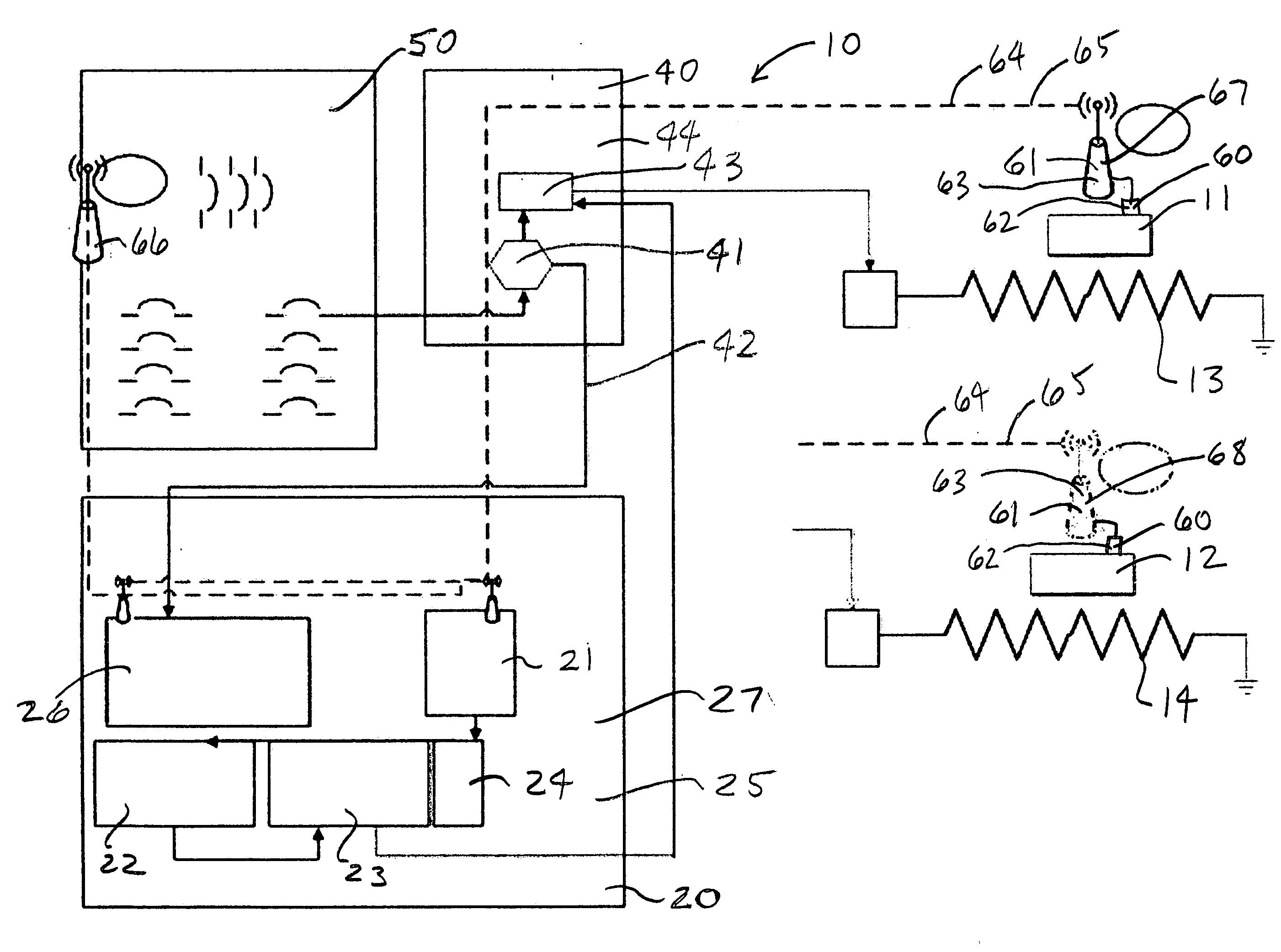
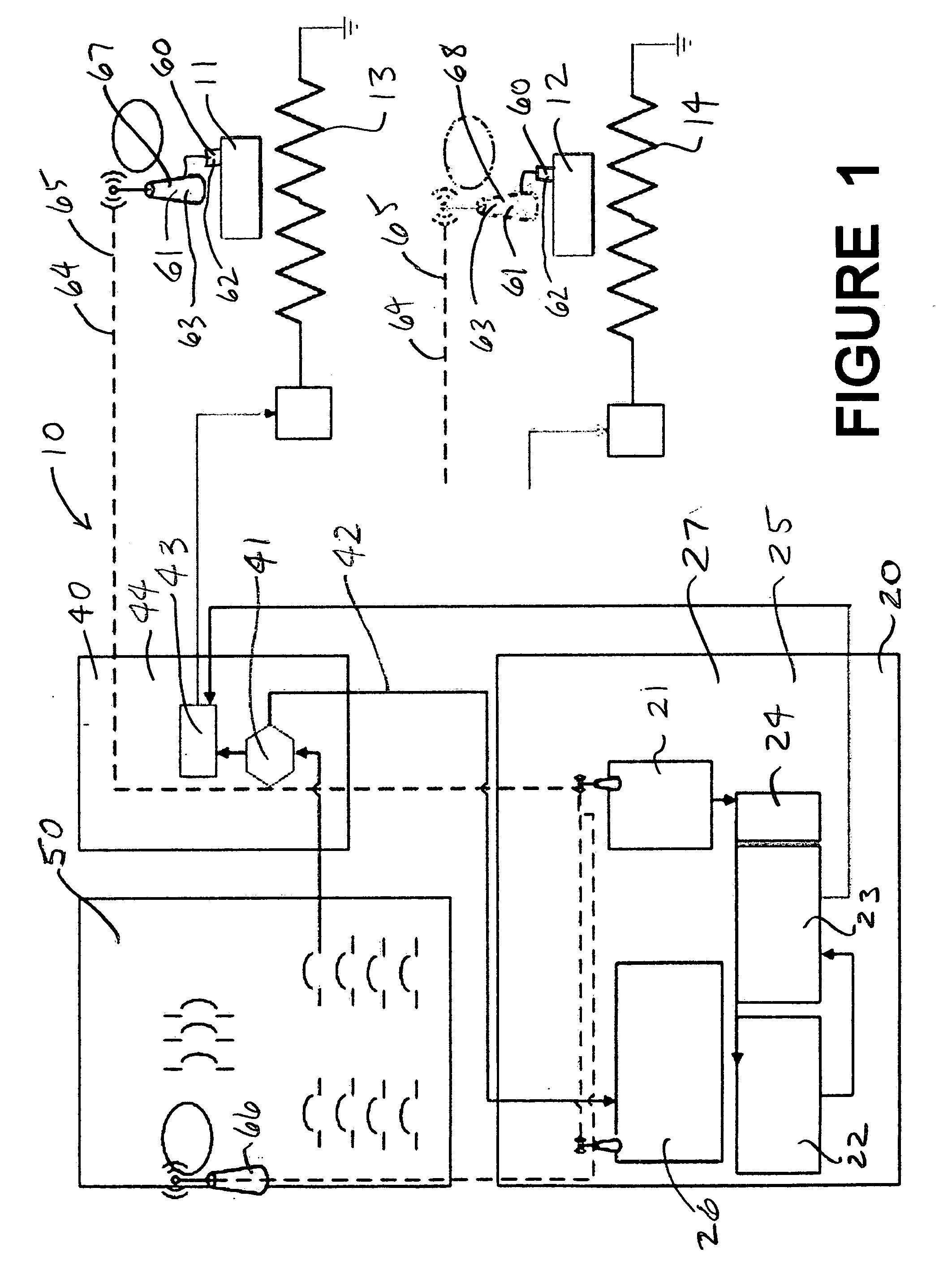
[0041]The remote sensor element 60, particularly in the first embodiment shown in FIG. 1, includes a plurality of remote temperature / vibration devices 61 (RTD's). Each of the remote temperature devices 61 includes a temperature sensor 62 that is capable of measuring an adjacent temperature, a vibration sensor capable of measuring vibration (frequency and / or amplitude) and also includes a MESH network transmitter or transceiver (radio) 63 (in the wireless case) (or a line driver in the hardwired case) capable of communicating a signal representing that temperature / vibration to the controller 22, through a communication link 64. That communication link 64 might be hardwired or might be a wireless communication link 65. One or more of the remote temperature devices (environmental temperature sensor) 66 is installed to measure environmental temperature within the facility, and other remote temperature devices / vibration (equipment temperature / vibration sensors) 67 and 68 are installed to...
third embodiment
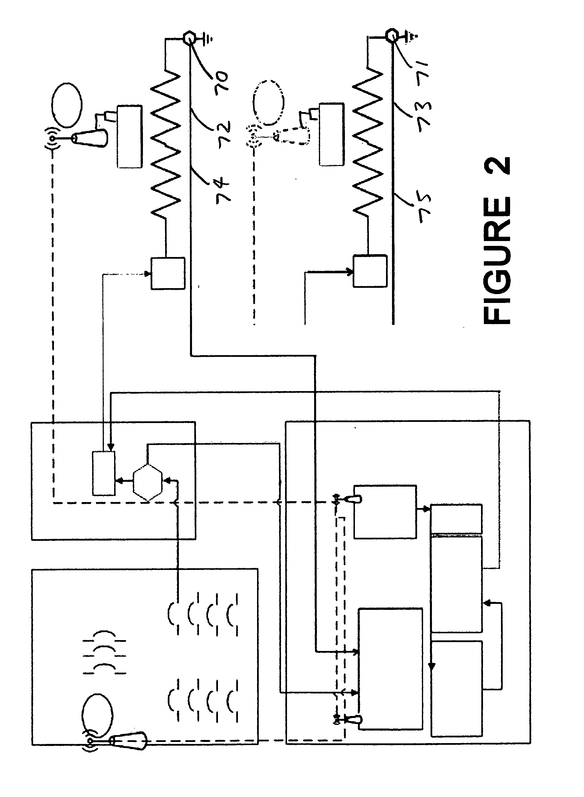
[0042]In a second and third embodiment of this invention, shown in FIGS. 2 and 3 respectively, the system includes a second current monitoring device 70 and 71 associated with each heater 11 and 12 respectively and adapted to monitor the return current from the heater and provide a signal representing that return current to the controller 22. This allows the system to compare the outgoing and returning currents in the heater circuit and thereby detect current leakage in heater circuit. The second current monitoring device 70 and 71 could be located remotely, for example, near the heater (assuming remote grounding), or could be mounted with the first circuit monitoring device 41 in the relay panel 40 (assuming a complete return line to the relay panel 40). The second current monitoring device 70 and 71 communicates its signal through a communication link 72 and 73 respectively (which could be either a hardwired communication link 74 and 75 respectively or a wireless communication lin...
PUM
 Abstract
Description
Claims
Application Information
 - R&D
- Intellectual Property
- Life Sciences
- Materials
- Tech Scout
- Unparalleled Data Quality
- Higher Quality Content
- 60% Fewer Hallucinations
Browse by: Latest US Patents, China's latest patents, Technical Efficacy Thesaurus, Application Domain, Technology Topic, Popular Technical Reports.
© 2025 PatSnap. All rights reserved.Legal|Privacy policy|Modern Slavery Act Transparency Statement|Sitemap|About US| Contact US: help@patsnap.com


