
Three-dimensional light supplementing lamp

A fill light, three-dimensional technology, applied in the field of lamps, can solve the problem of uneven light receiving of plants, and achieve the effects of being beneficial to plant growth, saving energy, and solving a single lighting method.

Pending Publication Date: 2018-12-25
LUMLUX CORP
View PDF0 Cites 1 Cited by
  • Summary
  • Abstract
  • Description
  • Claims
  • Application Information

AI Technical Summary

Problems solved by technology

[0004] The purpose of the present invention is to provide a three-dimensional supplementary light to solve the technical problem of uneven light received by plants in the prior art

Method used


Image

  • Three-dimensional light supplementing lamp
  • Three-dimensional light supplementing lamp
  • Three-dimensional light supplementing lamp

Examples


Embodiment 1

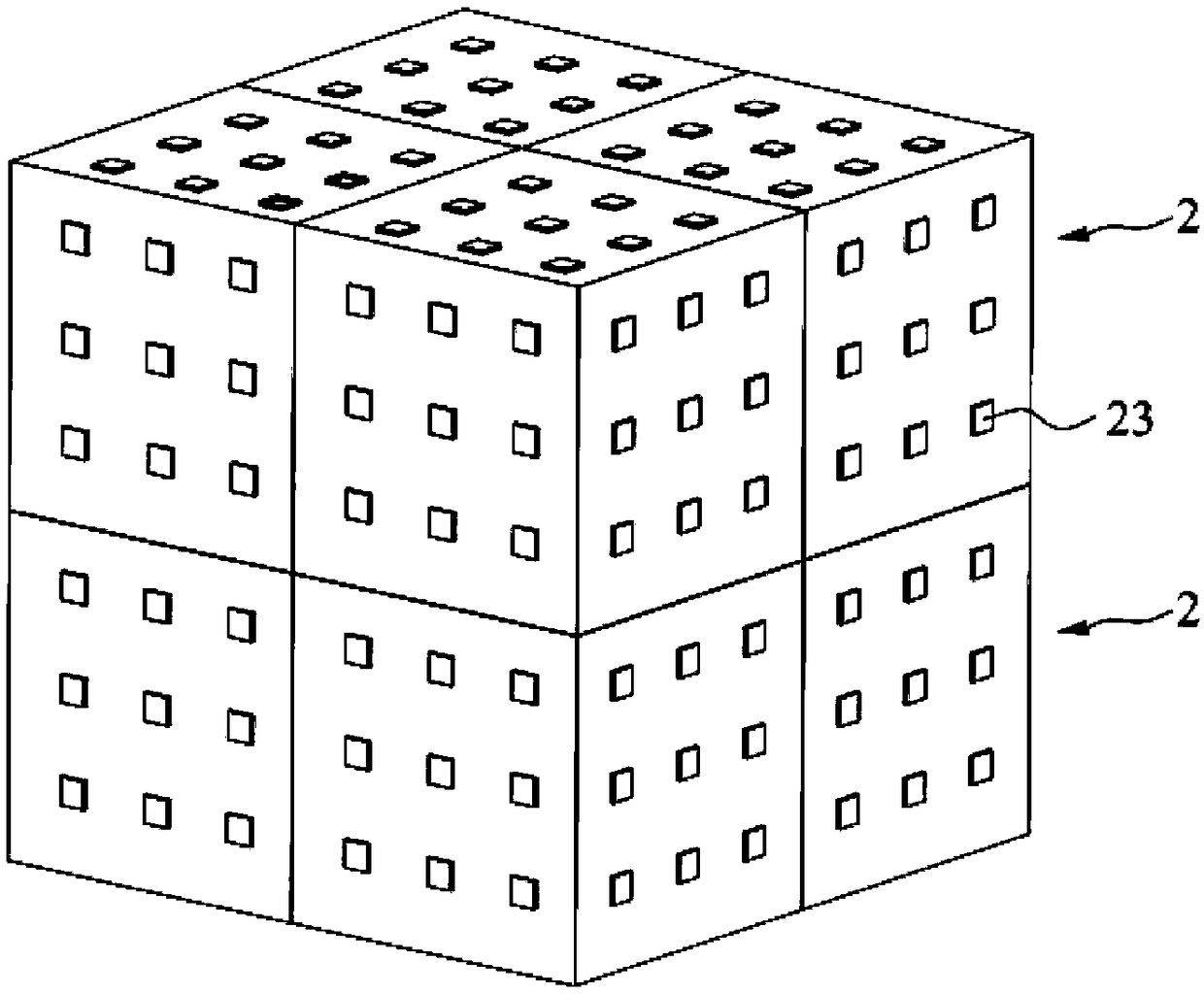
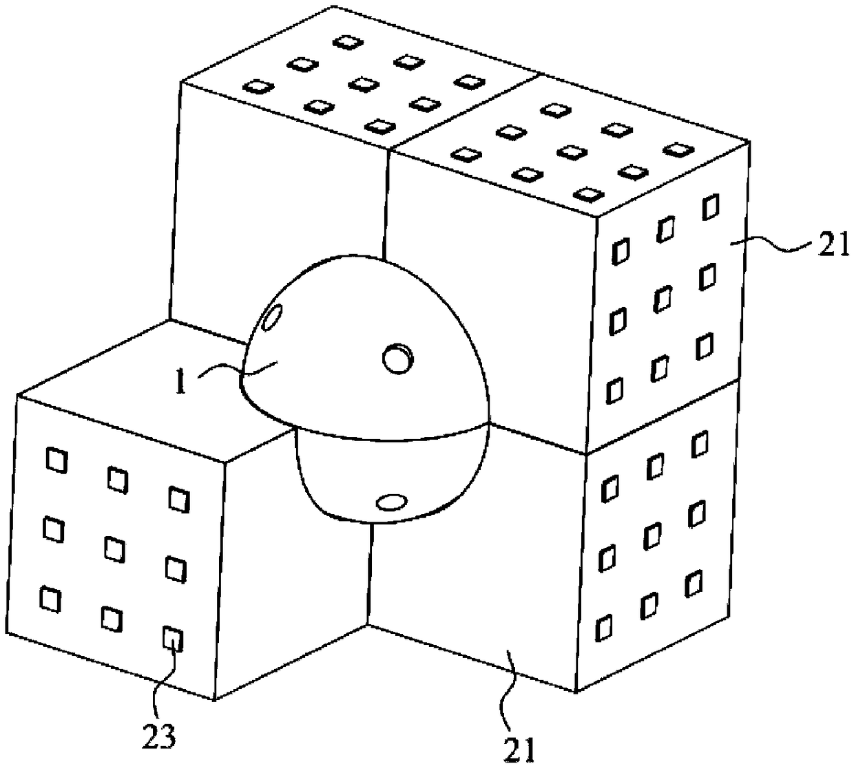
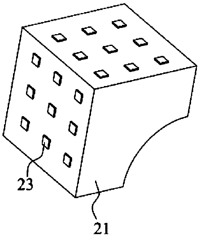
[0040] see Figure 1 to Figure 9 , the embodiment of the present invention provides a three-dimensional fill light, including a support 1 and a light-emitting base 2, the light-emitting base 2 is used for lighting, and the support 1 is used to provide support for the light-emitting base 2, and the three-dimensional fill light can be placed as required Go anywhere on the plant for deep lighting.

[0041] The support 1 includes at least two connecting parts 11, the connecting parts 11 constitute at least part of a sphere, and the connecting parts 11 can rotate around the central axis of the sphere; Several light-emitting substrates 2 are arranged on the axis. Three-dimensional lighting is realized without a reflector, so that the light-emitting base 2 can be illuminated from multiple surfaces and angles, and the plants receive light more uniformly; the connecting part 11 can rotate around the central axis, driving the light-emitting base 2 to rotate, and can realize multi-facet...

Embodiment 2

[0054] Figure 10 to Figure 14 Embodiment 2 is shown, in which components identical or corresponding to those in Embodiment 1 use the same reference numerals as in Embodiment 1. For simplicity, only the differences between Embodiment 2 and Embodiment 1 are described. The difference is that the supporting member 1 further includes several fixing parts 12 , connecting parts 11 are arranged between adjacent fixing parts 12 , and the connecting parts 11 and the fixing parts 12 are slidably connected. The setting of the fixing part 12 plays a role of supporting the connecting part 11 and ensures the structural strength.

[0055] Several fixing parts 12 are connected by a bracket 13 , and the bracket 13 includes three supporting shafts 131 connected vertically in pairs, and two ends of each supporting shaft 131 are connected with the fixing parts 12 . The connecting part 11 rotates around one of the supporting shafts 131 . The supporting shaft 131 can be of integral structure or ...


PUM


Abstract

The invention discloses a three-dimensional light supplementing lamp. The three-dimensional light supplementing lamp comprises a support piece and light-emitting matrices; the supporting piece comprises at least two connecting parts, and the connecting parts at least constitute part of a sphere, and can rotate around the central axis of the sphere; the light-emitting matrices are detachably connected with the connecting parts, and several light-emitting matrices are arranged around the central axis of each connecting part. The lamp can be placed at any position of plants for deep-level lighting according to demands; a reflector is not needed, three-dimensional lighting is achieved so that the light-emitting matrices can achieve multi-faced and multi-angle lighting, and the plants receive more uniform light; The connecting parts can rotate around the central axis of the sphere to drive the light-emitting matrices to rotate, and multi-faced light supplementing or spherical light supplementing can be achieved, which is more beneficial to plant growth and energy saving. The light-emitting matrices are detachably connected with rotating parts, local lighting can be achieved, and light supplementing is conducted according to demands of the plants. By means of the lamp, the problems are solved that a traditional plant light supplementing lamp has a single lighting mode, a fixed installation mode and low efficiency.

Description

technical field [0001] The invention relates to the technical field of lamps, in particular to a three-dimensional supplementary light. Background technique [0002] Illumination is a necessary condition for plant growth, and the use of light for photosynthesis is a key link in plant growth and synthesis of organic matter. In order to improve the light utilization rate of plants, enhance the synthesis of organic matter, promote plant growth, and increase yield, it is very necessary to use light instead of sunlight to supplement light for plants. [0003] Most of the existing plant supplementary light adopts the installation method of hoisting, which can only irradiate the plants at a fixed position and a fixed angle from high to low or from left to right. The plants receive uneven light, and the plants closest to the light source grow best. In order to obtain a larger illuminated area, some fill lights are equipped with reflectors to reflect and concentrate light, which ma...

Claims


Application Information

Patent Timeline
IPC IPC(8): A01G7/04F21S6/00F21V17/10F21V19/00F21V15/01F21V23/00F21V21/096F21Y115/10
CPCA01G7/04F21S6/004F21V15/01F21V17/10F21V19/001F21V21/096F21V23/003F21Y2115/10Y02P60/14
Inventor 周丽萍
Owner LUMLUX CORP
Learn More