Robot collision detection method and device

A technology of collision detection and robotics, applied in manipulators, manufacturing tools, etc., can solve the problem of high cost of robots, achieve good dynamic performance, high accuracy, and facilitate industrial promotion and application

Pending Publication Date: 2018-12-25
ZHUHAI GREE INTELLIGENT EQUIP CO LTD +1
View PDF5 Cites 11 Cited by
  • Summary
  • Abstract
  • Description
  • Claims
  • Application Information

AI Technical Summary

Problems solved by technology

[0005] Embodiments of the present invention provide a robot collision detection method and device, to at least solve the technical problem of using sensors to detect robot collisions in the prior art, resulting in high robot costs

Method used


Image

  • Robot collision detection method and device
  • Robot collision detection method and device
  • Robot collision detection method and device

Examples


Embodiment 1

[0024] According to an embodiment of the present invention, an embodiment of a collision detection method for a robot is provided. It should be noted that the steps shown in the flowchart of the accompanying drawings can be executed in a computer system such as a set of computer-executable instructions, and Although the logical sequence is shown in the flowchart, in some cases, the steps shown or described may be performed in a different order than here.

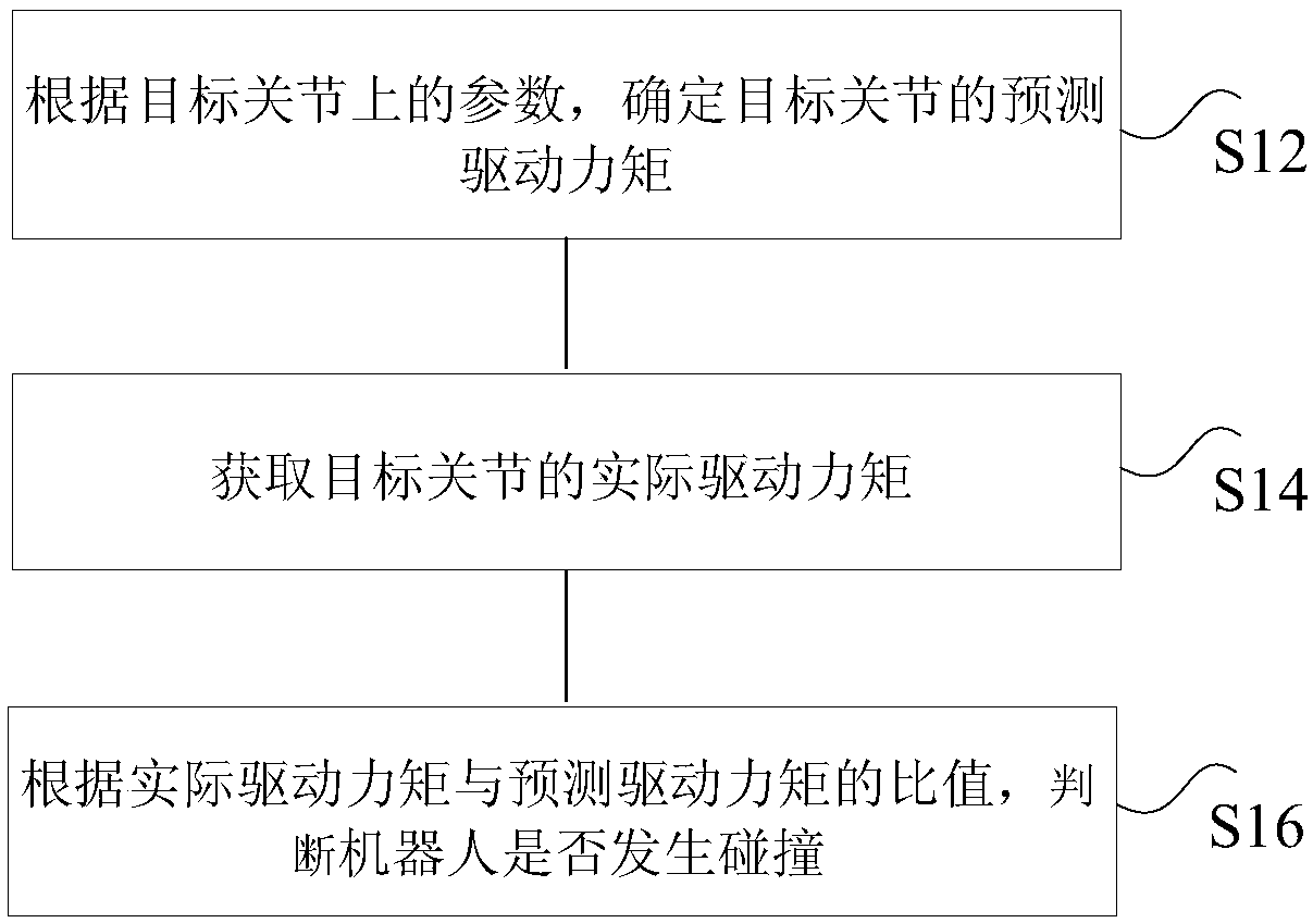
[0025] figure 1 Is a flowchart of the collision detection method of a robot according to an embodiment of the present invention, such as figure 1 As shown, the method includes the following steps:

[0026] Step S12: Determine the predicted driving torque of the target joint according to the parameters on the target joint.

[0027] In an optional solution, the aforementioned target joint may be any one or more of the many joints of the robot. The above-mentioned parameters can be the angle, angular velocity, and angular acceleratio...

Embodiment 2

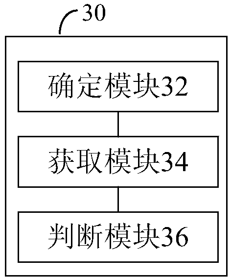
[0068] According to an embodiment of the present invention, a collision detection device for a robot is provided, image 3 Is a schematic diagram of a robot collision detection device according to an embodiment of the present invention, combined with image 3 As shown, the device includes:

[0069] The determining module 32 is configured to determine the predicted driving torque of the target joint according to the parameters on the target joint.

[0070] The obtaining module 34 is used to obtain the actual driving torque of the target joint.

[0071] The judging module 36 is used for judging whether the robot collides according to the ratio of the actual driving torque to the predicted driving torque.

[0072] It can be seen from the above that the foregoing embodiment of the present invention determines the predicted driving torque of the target joint based on the parameters of the target joint, obtains the actual driving torque of the target joint, and determines whether the robot...

Embodiment 3

[0091] According to an embodiment of the present invention, a storage medium is provided, the storage medium includes a stored program, wherein the device where the storage medium is located is controlled to execute the collision detection method of the robot in Embodiment 1 while the program is running.


PUM


Abstract

The invention discloses a robot collision detection method and device. The method comprises the steps that according to parameters on a target joint, a predicted driving moment of the target joint isdetermined, and an actual driving moment of the target joint is obtained; according to the specific value of the actual driving moment and the predicted driving moment, whether a robot collides or notis judged. Accordingly, a sensor does not need to be additionally arranged, the hardware structure of the robot does not need to be changed, the system development cost is reduced, and the technicalproblem that in the prior art, the sensor is used for detecting robot collision, and then the robot cost is high is solved.

Description

Technical field [0001] The present invention relates to the field of industrial robots, and in particular to a collision detection method and device for robots. Background technique [0002] An industrial robot is a multi-joint manipulator or a multi-degree-of-freedom machine device oriented to the industrial field. It can automatically perform work and is a machine that realizes various functions by its own power and control capabilities. It can be commanded by humans, or it can run in accordance with a pre-arranged program. [0003] In the path planning of industrial robots, it is necessary to avoid moving or static obstacles in real time. The main function of collision detection is to reduce the impact of collision force on the robot body, avoid damage to the robot body or surrounding equipment, and even casualties. At present, collision detection methods are mainly divided into methods of adding sensors outside the robot and adding or directly reading internal information ins...

Claims


Application Information

Patent Timeline
Patent Type & Authority Applications(China)
IPC IPC(8): B25J19/06
CPCB25J19/06
Inventor 冯晶晶谢黎余杰先钟文涛杨裕才
Owner ZHUHAI GREE INTELLIGENT EQUIP CO LTD
Why Eureka
Try Eureka