Upper-traction adjusting type assembled cofferdam

A combined cofferdam and adjustment technology, applied in construction, infrastructure engineering, etc., can solve the problems of not well matched slope slope, leakage of cofferdam side walls and slopes, etc. The overall connection strength and the overall structure are simple and stable.

Pending Publication Date: 2018-12-25
STATE GRID CORP OF CHINA +2
View PDF4 Cites 0 Cited by
  • Summary
  • Abstract
  • Description
  • Claims
  • Application Information

AI Technical Summary

Problems solved by technology

[0003] The present invention aims at the problem that the current existing combined cofferdams cannot match the slope slope well, which leads to large gaps between the side walls of the cofferdam and the slope and thus water leakage, and provides a method that can automatically adapt to different slope slopes The combined cofferdam, and the U-shaped upper draw beam is used to connect the wading bottom wall and the two side walls of the combined cofferdam to improve the overall connection strength, and the U-shaped upper draw beam has the advantages of flexible installation and disassembly

Method used


Image

  • Upper-traction adjusting type assembled cofferdam
  • Upper-traction adjusting type assembled cofferdam
  • Upper-traction adjusting type assembled cofferdam

Examples


Embodiment 1

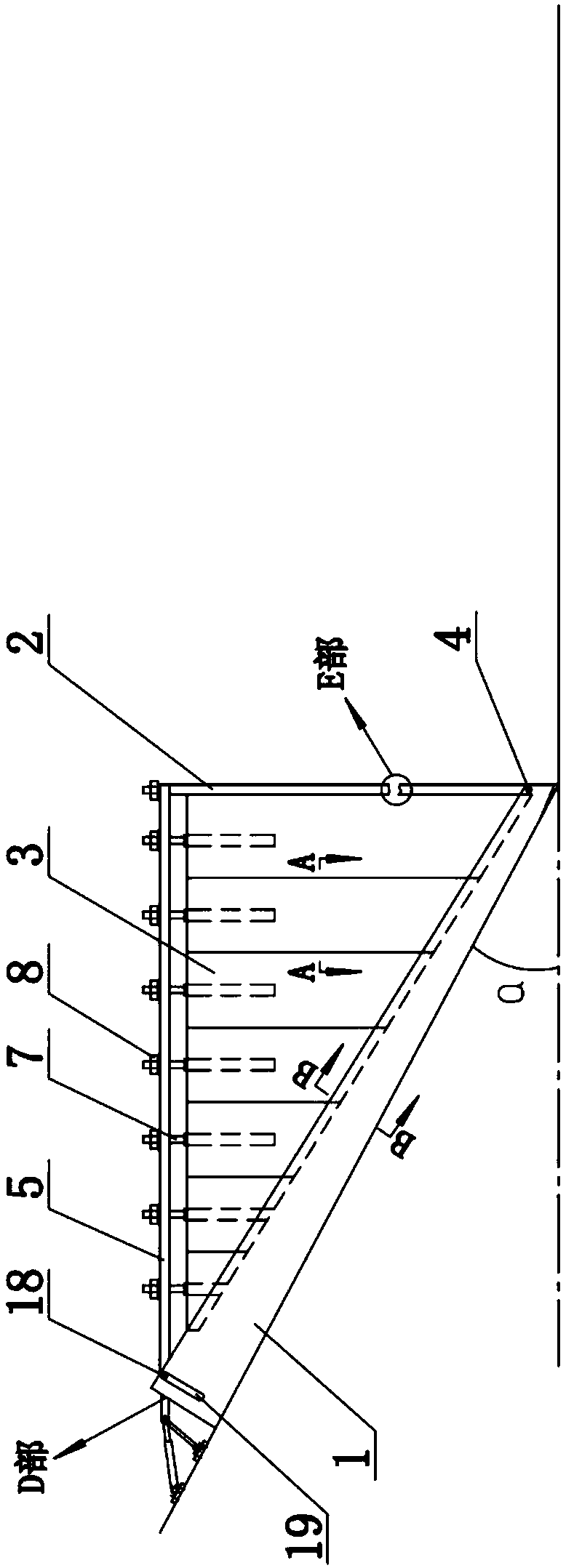
[0022] Embodiment 1: The main body of the combined cofferdam includes a wading bottom wall 2 and two side walls 3, and also includes structural components such as an adjustment seat, a U-shaped upper draw beam 5, and a U-shaped parallel clamping seat 1.

[0023] Wherein, the wading bottom wall 2 is an integrated wallboard, or a combined wallboard composed of multiple bottom boards butted in sequence, and a convex-concave clamping structure 9 and a sealing water-stop layer are arranged on the butt joint surface. The side walls 3 may also be integral triangular wall panels, or may be composed of a plurality of side panels butted in sequence, and a convex-concave clamping structure 9 and a sealing water-stop layer are arranged on the butted surfaces. The sealing water-stop layer is usually sealed with a rubber layer. The purpose of the combined wading bottom wall 2 and side walls 3 is to provide convenience for transfer after disassembly.

[0024] set a like Image 6 A U-shaped...

Embodiment 2

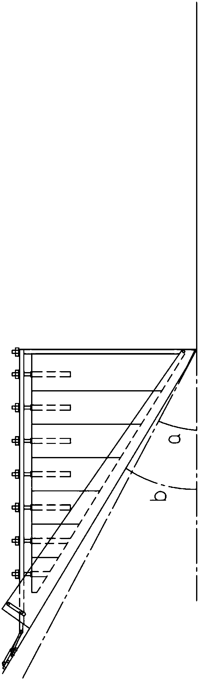
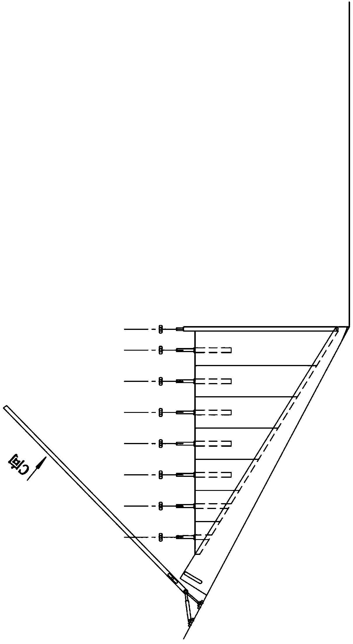
[0028] Embodiment 2: The two side walls 3 of the embodiment 1 are composed of multiple side plates connected in sequence, and on the basis of setting the convex-concave clamping structure 9 and the sealing water-stop layer on the butt surface, the side walls 3 are set to be freely adjustable structure. Such as Figure 4 As shown, two adjacent side panels are convex-convex butted, so that the side panels are mutually restrained and can only slide vertically. Vertical sliding is allowed, and the height adjustment of the side wall 3 can be realized by using vertical sliding, and multiple side plates are respectively inserted into the U-shaped parallel deck 1 below it, regardless of the angle of the U-shaped parallel deck 1 with the slope angle How to change, each side plate can reach the ability of inserting U-shaped parallel deck 1, can be fixed with inner sealing waterproof layer 11 on the two inner sidewalls of U-shaped parallel deck 1, thereby realize the sealing of side wal...

Embodiment 3

[0030] Embodiment 3: On the basis of Embodiment 1, the adjustment and positioning of the U-shaped parallel deck 1 and the U-shaped upper draw beam 5 are carried out. The non-wading end of the U-shaped parallel deck 1 is provided with a vertical sliding hole 18 perpendicular to its bottom surface, and horizontal sliding holes 17 are respectively provided on both sides of the U-shaped upper drawing beam 5 near the hinged end. The U-shaped parallel deck 1 is not The vertical sliding hole 18 at the wading end is hinged in the horizontal sliding hole 17 of the U-shaped parallel clamp 1 through a sliding shaft 19 .


PUM


Abstract

The invention discloses an upper-traction adjusting type assembled cofferdam which comprises a wading bottom wall and two side walls, wherein the wading bottom wall and the two side walls form a cofferdam main body; adjusting bases are hinged with both ends of a U-shaped upper-traction beam through support hinge pins and are positioned right above the wading bottom wall and the two side walls; a U-shaped parallel clamping base is arranged below the two side walls in a sleeving manner; wading ends of the U-shaped parallel clamping base are hinged below the wading bottom wall through root hingepines; non-wading ends of the U-shaped parallel clamping base are connected with both sides of the U-shaped upper-traction beam. As the U-shaped upper-traction beam is connected with the wading bottomwall and the two side walls to form an entity, the overall connection strength of the cofferdam can be improved; the lower ends of the U-shaped upper-traction beam are supported on the wading bottomwall, and the two side walls are tracked and lifted on both sides of the U-shaped upper-traction beam through positioning holes, traction screw rods and adjusting screw nuts. The upper-traction adjusting type assembled cofferdam is simple and stable in overall structure, easy to construct and implement and very convenient to both mount and dismount.

Description

technical field [0001] The invention belongs to the cofferdam improvement technology in the field of water conservancy engineering, and in particular relates to an upper traction adjustable combined cofferdam. Background technique [0002] During the long-term use of rivers and channels, it is inevitable that the side slopes will be partially scoured, cracked and other damage phenomena. Long-term water flow will also make the cracks and gaps in the side slopes of rivers and channels continue to expand, and even threaten the safety of the entire channel and the residents on both sides of the channel. The safety of life, bring economic and property losses to the broad masses of the people, slope care is a long-term continuous work. The traditional cofferdam has a heavy workload due to its complex structure during the construction process, and it is not easy to dismantle and move, and it is very inconvenient to use. The combined cofferdam has the advantages of detachable and t...

Claims


Application Information

Patent Timeline
Patent Type & Authority Applications(China)
IPC IPC(8): E02D19/04
CPCE02D19/04
Inventor 王坤王从显李长胜罗胤徐学兵董政淼靳国云曹永闯赵俊杰杨恒乐秦连乐
Owner STATE GRID CORP OF CHINA
Why Eureka
Try Eureka