Underground tail end hydraulic switch
A technology of hydraulic switch and hydraulic sliding sleeve, which is applied in wellbore/well components, wellbore/well valve devices, earthwork drilling and production, etc. It can solve the problem of no downhole pipeline end device controlling hydraulic switch, no existing reference technology, Structure and application problems, to achieve the effect of eliminating the need for locking devices, compact and reasonable structure, and ensuring control accuracy
- Summary
- Abstract
- Description
- Claims
- Application Information
AI Technical Summary
Problems solved by technology
Method used
Image

Examples
Embodiment 1
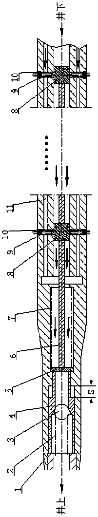
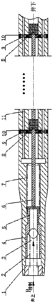
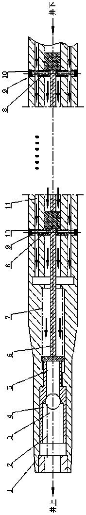
[0031] The downhole terminal hydraulic switch of this embodiment includes a housing, a ball seat hydraulic sliding sleeve assembly, a connecting plate, a push rod, and an opening and closing mechanism. The opening and closing mechanism includes a valve core, a valve core control spring matched with the valve core, and a casing. , the bushing is set on the push rod. The ball seat hydraulic sliding sleeve assembly includes a hydraulic sliding sleeve, a sphere arranged in the hydraulic sliding sleeve, and a sphere return spring. A counterbore is arranged in the hydraulic sliding sleeve, and the sphere return spring can press the sphere to the bottom of the counterbore. The two sides of the connecting plate are respectively connected with the ball seat hydraulic sliding sleeve assembly and the push rod, and the inner side of the housing is provided with a hole matching with the connecting plate; the hole is provided with a pressure control spring interacting with the connecting pla...
PUM
 Abstract
Description
Claims
Application Information