Water and sand separation and measurement device in water and sand uprush test system

A test system and metering device technology, applied to the measuring device, by removing certain components to weigh, weigh, etc., can solve the problem of insufficient water head pressure, inability to measure water and sand surges separately, and inconvenient tests, etc. problem, to achieve the effect of preventing deviation

Active Publication Date: 2018-12-25
LINYI UNIVERSITY
View PDF8 Cites 3 Cited by
  • Summary
  • Abstract
  • Description
  • Claims
  • Application Information

AI Technical Summary

Problems solved by technology

[0003] When mining coal mines, it is easy to induce overlying rock movement. Due to the concealment of underground mining engineering, it is difficult to study the mechanism of water and sand migration and inrush in overlying rock cracks caused by coal mining with the help of on-site observation. It is an effective means to solve this problem. However, in the existing water-sand inrush test, the inrush volume of water and sand cannot be measured separately, and the sand in the test chamber has not been compressed to a certain extent before the test. Because of the limitation of the test space, it can only be obtained by adjusting the height of the water tank or the height of the water surface in the water tank to obtain different head pressures, which is very difficult in the test. Convenience, for this reason, we propose a water and sand separation and metering device in the water and sand inrush test system to solve the above problems

Method used


Image

  • Water and sand separation and measurement device in water and sand uprush test system
  • Water and sand separation and measurement device in water and sand uprush test system
  • Water and sand separation and measurement device in water and sand uprush test system

Examples


Embodiment Construction

[0029] The following will clearly and completely describe the technical solutions in the embodiments of the present invention with reference to the accompanying drawings in the embodiments of the present invention. Obviously, the described embodiments are only some, not all, embodiments of the present invention.

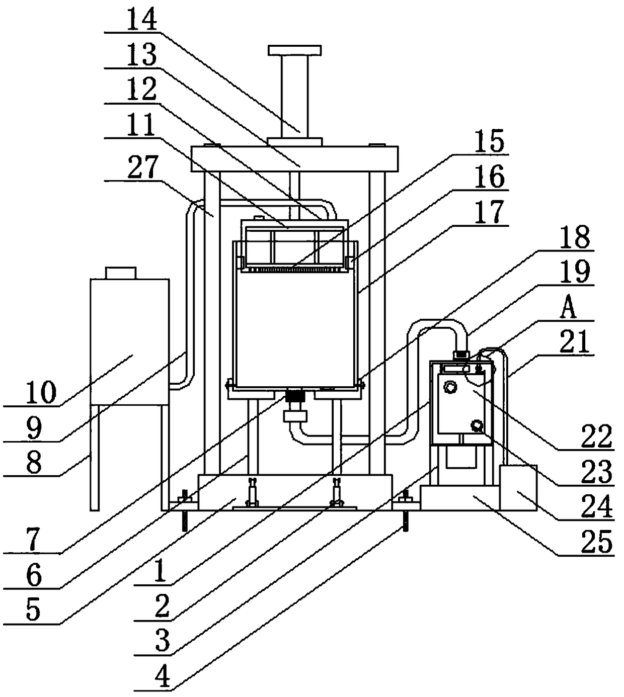
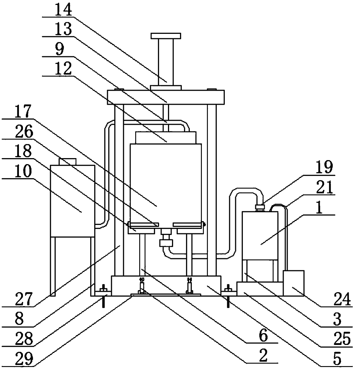
[0030] refer to Figure 1-7 , a water-sand inrush separation and metering device in a water-sand inrush test system, including an operating platform 5, conveniently supports the test chamber 17, prevents the test chamber 17 from being disassembled during each test, and avoids causing damage to the test chamber 17. wear and tear, the upper end of the console 5 is fixed with four fixed rods 27, the upper ends of the four fixed rods 27 are jointly fixed with a beam 13, the upper end of the beam 13 is fixed with an oil cylinder 14, and the piston rod of the oil cylinder 14 runs through the side wall of the beam 13 and extends To the lower end of the crossbeam 13, four be...


PUM


Abstract

The invention discloses a water and sand separation and measurement device in a water and sand uprush test system. The water and sand separation and measurement device comprises an operation platform,and four fixing rods are fixedly arranged at the upper end of the operation platform. The upper ends of the four fixing rods are together fixedly provided with a cross beam, and an oil cylinder is fixed to the upper end of the cross beam. A piston rod of the oil cylinder penetrates through the side wall of the cross beam and extends to the lower end of the cross beam, and four bearing rods are fixed to the upper end of the operation platform. Clamping devices are arranged at the upper ends of the bearing rods, and the four clamping devices are all arranged on one side of a test chamber in a butting mode. A water sump is arranged at the upper end of the test chamber in a penetrating mode, the tail end of the piston rod of the oil cylinder is fixed at the upper end of the water sump, and anair outlet hole is formed in the upper end of the water sump. Through the water and sand separation and measurement device, the problem of insufficient pressure during testing is solved, the problemthat sand soil can not be compacted is also solved, the function of respectively measuring the water uprush amount and the sand uprush amount is achieved, the accuracy of testing data is improved, operation is simple, and using is convenient.

Description

technical field [0001] The invention relates to the technical field of water and sand, in particular to a water and sand separation and metering device in a water and sand inrush test system. Background technique [0002] At present, the use of coal is increasing year by year, and the amount of coal mining is also increasing. Large thickness, shallow buried depth, thin bedrock, and thick loose sand overlying are the typical occurrence characteristics of coal in the western region. The overlying rock movement induced by the mining of this kind of coal seam is strong and has a wide range, and it is difficult for the overlying rock to form a relatively stable support structure. The water-sand mixture with good water quality and high sand content collapses into the underground working face along the cracks in the mining overlying rock, resulting in frequent accidents that cause property losses and even casualties, posing a great threat to the safe production of mines. To ensure...

Claims


Application Information

Patent Timeline
Patent Type & Authority Applications(China)
IPC IPC(8): G01N5/04G01G17/04
CPCG01G17/04G01N5/04G01N5/045
Inventor 王海龙刘珂铭贾传洋于献彬张贵彬宋小园李伟
Owner LINYI UNIVERSITY
Why Eureka
Try Eureka