A sliding charging joint and charging pile

A charging connector and sliding technology, applied in the field of sliding charging connectors, can solve problems such as hidden safety hazards, dust and insect short circuits, and achieve the effect of expanding the use area

Active Publication Date: 2020-09-08
SHENZHEN PUFANG ENVIRONMENTAL PROTECTION DEV
View PDF7 Cites 0 Cited by
  • Summary
  • Abstract
  • Description
  • Claims
  • Application Information

AI Technical Summary

Problems solved by technology

[0003] In the above-mentioned movable plug-in system, since the opening of the notch of the grooved guide rail is relatively large, and the energized metal strip inside the grooved guide rail is on the same plane as the notch, the metal strip connected to the external electricity is fully exposed, and there is a huge Potential safety hazards, and dust, flying insects, etc. can enter the inside of the grooved guide rail and cause a short circuit

Method used


Image

  • A sliding charging joint and charging pile
  • A sliding charging joint and charging pile

Examples


Embodiment 1

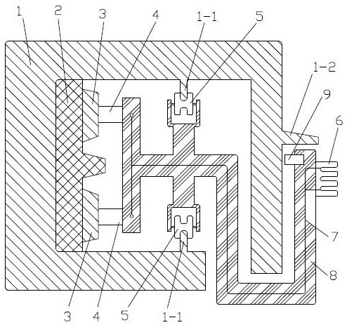
[0012] attached figure 1 It is a schematic structural diagram of the first embodiment of the sliding charging connector of the present invention. The sliding charging connector in the illustration includes a frame-shaped shell 1 with a gap left in the cross section, a socket bracket 8, a charging socket 6 and a pair of conductive metal tracks 3. The notch is arranged on the lower side of the casing 1 to prevent dust from entering and electric shock accidents. The pair of conductive metal rails 3 are fixedly installed in the casing 1 along the length direction of the casing 1. An insulating gasket 2 is arranged between the contact side of the conductive metal rail 3 and the casing 1. There is a limit guide rail 1-1 parallel to the conductive metal track 3, and the socket bracket 8 is slidably connected with the limit guide rail 1-1 through a pair of pulleys 5 corresponding to the position limit guide rail 1-1 on it, and is fixedly installed on the The middle part of the pulley...

Embodiment 2

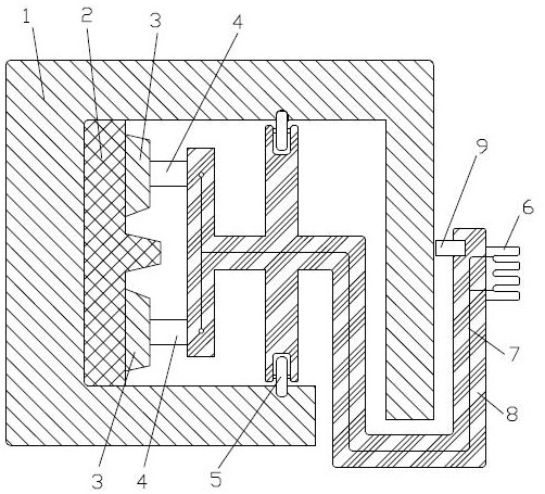
[0015] attached figure 2 It is a schematic structural diagram of the second embodiment of the sliding charging joint of the present invention, which is basically the same as the first embodiment. The difference is that the limit track is an inner groove type, and the embedded pulley 5 can slide in the limit track.


PUM


Abstract

A sliding type charging joint is provided. The invention solves the defect that a charging socket is fixed and inconvenient to use in the prior art. The charging joint comprises a frame-shaped shell with a notched cross section, a socket support, a charging socket and a pair of conductive metal tracks, the pair of conductive metal tracks are fixedly mounted in the shell along the length directionof the shell, an insulating gasket is arranged between the conductive metal tracks and the contact side of the shell, limit guide rails parallel to the conductive metal rails are arranged on a pair ofopposite inner sides of the shell, the socket bracket is slidably connected with the limit guide rails through a pair of pulleys corresponding to the limit guide rails in position thereon, the socketbracket is fixedly provided with a pair of conductive sliding elastic pieces at one end of the shell, the conductive sliding elastic pieces abut on the conductive metal tracks respectively, the charging socket is installed on the part of the socket bracket protruding out of the shell through a notch, and the socket bracket is provided wires connected with the conductive sliding elastic pieces andthe charging socket. The charging joint is mainly used on a charging pile, which is safe, reliable, convenient to use and cost-saving.

Description

technical field [0001] The invention relates to a charging connector and a charging pile, in particular to a sliding charging connector. Background technique [0002] In order to allow flexible movement of the plug-in position, the utility model with application number 201720497042.X discloses a movable plug-in system, which includes a grooved guide rail, a sliding device and a plug-in row. A number of metal strips connected to the external electricity are laid. The sliding device is set in the groove of the grooved guide rail and is slidably connected with the grooved guide rail. There are several metal sheets on the outside of the sliding device. The metal sheet and the metal strip are in one-to-one contact connection. The row and the metal sheet are connected through the plug-in wire circuit. [0003] In the above-mentioned movable plug-in system, since the opening of the notch of the grooved guide rail is relatively large, and the energized metal strip inside the groove...

Claims


Application Information

Patent Timeline
Patent Type & Authority Patents(China)
IPC IPC(8): H01R25/14H01R13/52H01R13/44B60L53/16B60L53/31
CPCH01R13/44H01R13/52H01R13/5213H01R25/14H01R25/142H01R25/145H01R2201/26Y02T10/70Y02T10/7072Y02T90/12Y02T90/14
Inventor 胡伟孙洪波金宣华黄鸿飞麦连锋卢仿胡雪莹胡红
Owner SHENZHEN PUFANG ENVIRONMENTAL PROTECTION DEV
Why Eureka
Try Eureka