
Construction method of laser resonator with large folding angle

A technology of laser resonator and construction method, which is applied in the direction of lasers, laser components, phonon exciters, etc., can solve problems such as complexity, affecting the use of optical components, and resonant cavities beyond the stable zone, so as to achieve simple design, simple structure, The effect of shortening the cavity length

Inactive Publication Date: 2018-12-25
XIAN TECH UNIV
View PDF4 Cites 0 Cited by
  • Summary
  • Abstract
  • Description
  • Claims
  • Application Information

AI Technical Summary

Problems solved by technology

In addition, the design of some folded cavities will cause crossing of the optical paths in the cavity, which will affect the placement of optical components on the one hand; on the other hand, increasing the cavity length will easily cause the resonator to exceed the stable region, which is not conducive to the design of the laser resonator. Thermal effects during high-power operation also very serious
[0003] Reducing the incidence angle of the spherical mirror can reduce astigmatism, but at the same time it will seriously affect the use of optical components in the resonator, for example: nonlinear optical crystals, optical one-way devices and other components are difficult to put into the resonator
The commonly used astigmatism compensation method is to put a specially designed Brewster plate or lens in the cavity to offset the optical path difference of the laser beam in the cavity in two directions perpendicular to each other, but inserting optical elements in the cavity will bring loss And affect the stability of the system, and the system is complex
Based on the transmission characteristics of Gaussian beams, astigmatism can also be compensated with the help of multiple concave mirrors, but this method requires complex calculations and has the problem of complex structure

Method used


Image

  • Construction method of laser resonator with large folding angle
  • Construction method of laser resonator with large folding angle
  • Construction method of laser resonator with large folding angle

Examples


Embodiment Construction

[0016] The present invention will be described in detail below with reference to the drawings and embodiments.

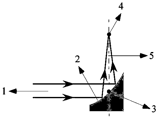
[0017] The design principle of the present invention is to separate any curved surface at the non-central axis of the rotationally symmetrical paraboloid as a reflection surface, thereby realizing the separation of the incident beam and the focused beam.

[0018] see figure 1 , a method for constructing a laser resonant cavity with a large folding angle provided by the present invention is to set an off-axis parabolic mirror in the cavity, the parallel light beam 1 is incident on the off-axis parabolic mirror 2, and is reflected and focused by the off-axis parabolic mirror 2, and the incident light The distance from the center 3 to the focal point 4 is the reflective focal length, and the angle between the incident light and the reflected light 5 is called the off-axis angle, which can be selected from 90º to 180º.

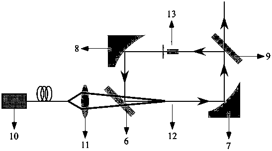
[0019] see figure 2 , what the present inventi...


PUM


Abstract

A construction method of a laser resonator with large folding angle is provided. An off-axis paraboloid mirror is arranged in a cavity, parallel beams enter the off-axis paraboloid mirror and are reflected and focusing by the off-axis paraboloid mirror, the distance from the center of the incident light to the focal point is the reflection focus, and angle between the incident light and reflectedlight is between 90 degrees and 180 degrees. According to the invention, optical elements can be inserted into the resonant cavity without constraint, and various necessary functions can be realizedsimply and efficiently. The optical path in the resonant cavity constructed by the method provided by the invention has no crossing, can effectively shorten the cavity length, is favorable for the design of the resonant cavity, and is particularly suitable for the traveling wave cavity with high power operation.

Description

technical field [0001] The invention relates to the technical field of laser device preparation, in particular to a method for constructing a laser resonant cavity with a large folding angle. Background technique [0002] As one of the three major components of laser devices, the role of resonators is crucial, and it is the core factor for laser devices to achieve various special properties. According to the structure, the laser resonator can be divided into two types: linear resonator and folded cavity. The realization of some special laser performance must rely on the folded cavity, such as the nonlinear frequency conversion of the inner cavity requires the laser beam to be highly focused, and the traveling wave cavity requires the laser to cyclically oscillate. Wait, of course the reflection loss of the folded cavity can be ignored, but there must be a spherical mirror as the folded mirror. The essential difference between the linear resonant cavity and the folded cavity...

Claims


Application Information

Patent Timeline
Patent Type & Authority Applications(China)
IPC IPC(8): H01S3/081
CPCH01S3/0816
Inventor 王垚廷张丽丽王党社张瑞红时文嘉张艳超
Owner XIAN TECH UNIV
Learn More