Key switch

A technology of switches and buttons, which is applied in the field of button switches, can solve problems such as flexible restrictions on the internal space configuration of buttons, false triggers, etc., and achieve the effect of improving trigger accuracy

Active Publication Date: 2018-12-25
DARFON ELECTRONICS (SUZHOU) CO LTD +1
View PDF9 Cites 4 Cited by
  • Summary
  • Abstract
  • Description
  • Claims
  • Application Information

AI Technical Summary

Problems solved by technology

However, in the above design, since both the optical emitter and the optical receiver must be arranged between the keycap and the bottom plate, the flexibility of the internal space configuration of the key is often limited and it is easy to cause light from the optical emitter to pass through the interior of the key. False triggering of components (such as keycaps, supports, etc.) reflecting and accidentally incident on the optical receiver

Method used


Image

  • Key switch
  • Key switch
  • Key switch

Examples


Embodiment Construction

[0031] The following descriptions of the various embodiments refer to the accompanying drawings to illustrate specific embodiments in which the present invention can be practiced. The directional terms mentioned in the present invention, such as "upper", "lower", "front", "rear", "left", "right", "side", etc., are only referring to the directions of the attached drawings. Therefore, the directional terms used are used to illustrate and understand the present invention, but not to limit the present invention.

[0032] In the following embodiments, the same parts are denoted by the same symbols in different drawings.

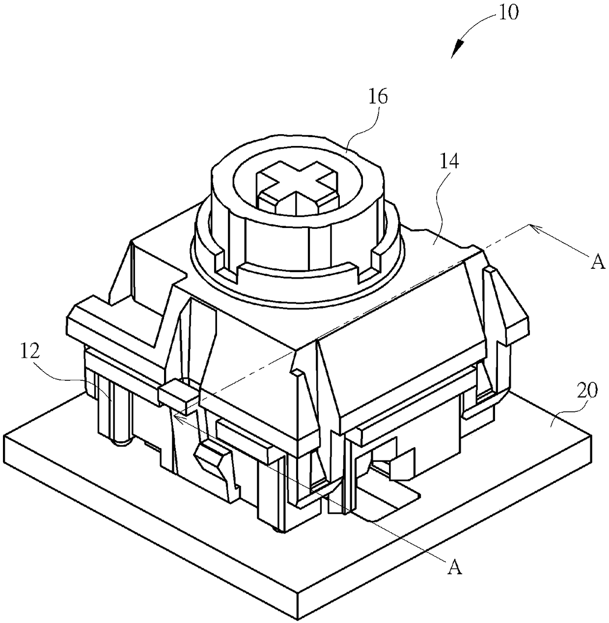
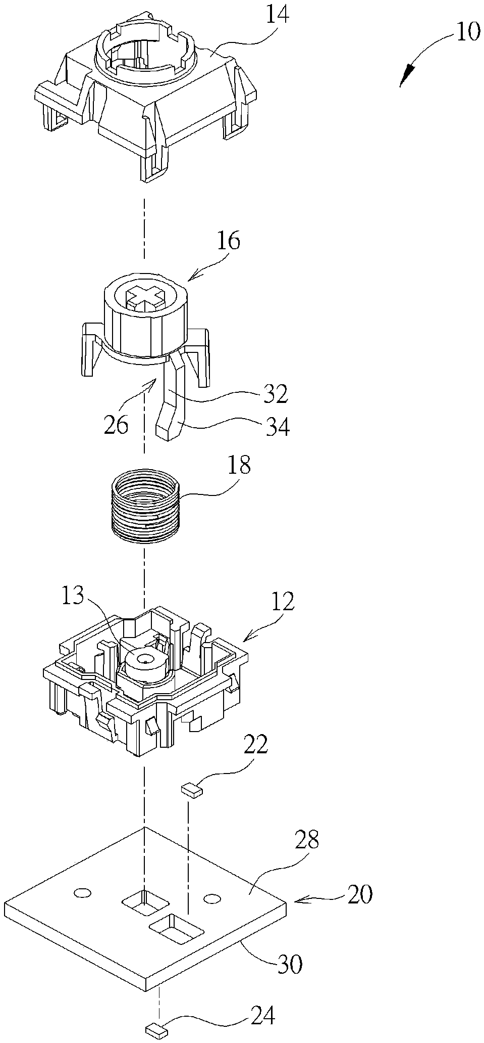
[0033] see figure 1 as well as figure 2 , figure 1 It is a three-dimensional schematic diagram of a key switch 10 proposed according to an embodiment of the present invention, figure 2 for figure 1 The exploded schematic diagram of the key switch 10, the key switch 10 can be connected with a keycap (not shown) to form a button that can be pressed by the use...


PUM


Abstract

The invention discloses a key switch, which comprises a base, an upper cover, a sleeve member, an elastic member, a circuit board, an optical path guide structure, an optical emitter and an optical receiver. The upper cover is arranged on the base. The sleeve member is rotatably sleeved on the positioning post of the base and movably passes through the upper cover to connect the key cap. The elastic member abuts against the sleeve member and the base. The circuit board is arranged under the base. The optical path guide structure is formed to extend downwardly from the sleeve member. The optical emitter and the optical receiver are respectively arranged on two opposite surfaces of the circuit board, and the light of the optical emitter is incident into the optical path guiding structure forreflection to the optical receiver. When the key cap is pressed, the optical path guiding structure generates a trigger signal as the sleeve member moves downward to conduct or block transmission ofthe optical path established by the optical emitter and the optical receiver through the guidance of the optical path guiding structure. The invention can improve the triggering accuracy of the key switch and the problems of easy wear and tear of the switch assembly and complicated welding manufacturing process.

Description

technical field [0001] The invention relates to a key switch, in particular to a key switch which uses an optical path guiding structure to conduct or block the optical path transmission between an optical transmitter and an optical receiver. Background technique [0002] As far as current personal computer usage habits are concerned, the keyboard is one of the indispensable input devices for inputting characters, symbols or numbers. Not only that, but all consumer electronic products in daily life or large-scale processing equipment used in the industry need to be equipped with key structures as input devices to operate the above-mentioned electronic products and processing equipment. [0003] In practical applications, in order to effectively improve the accuracy of button triggering and solve the problems of easy wear and tear of switch components and complicated welding manufacturing process caused by mechanical button trigger design, optical trigger design has been prop...

Claims


Application Information

Patent Timeline
Patent Type & Authority Applications(China)
IPC IPC(8): H03K17/96H03K17/968
CPCH03K17/9638H03K17/968H03K2217/94108
Inventor 王勇智杨宸谢育群刘家宏
Owner DARFON ELECTRONICS (SUZHOU) CO LTD
Why Eureka
Try Eureka