Eureka AIR delivers breakthrough ideas for toughest innovation challenges, trusted by R&D personnel around the world.

Working method of high-precision stamping die which is easy to replace

A technology of stamping dies and working methods, which is applied in the direction of forming tools, manufacturing tools, metal processing equipment, etc., can solve the problems of device replacement, low stamping precision, and poor practical performance, and achieve simple structure, high stamping precision, and improved precision. Effect

Active Publication Date: 2018-12-28
中山市祥亿精密五金模具制品有限公司
View PDF6 Cites 6 Cited by
  • Summary
  • Abstract
  • Description
  • Claims
  • Application Information

AI Technical Summary

Problems solved by technology

[0002] Stamping die is a special process equipment for processing materials into parts in cold stamping processing, called cold stamping die, stamping is at room temperature, using the mold installed on the press to apply pressure to the material to make it separate or Plastic deformation, so as to obtain a press processing method for the required parts. During the working process of the stamping die, different dies are often replaced for stamping due to the structure of the stamping part and the stamping production requirements, but the existing devices are often not able to quickly It is better to replace it, especially the existing stamping dies have low positioning accuracy for some stamping parts of the opposite sex (such as the stamping parts of the opposite sex in the shape of a ring or a truncated cone), resulting in low stamping accuracy and poor practical performance

Method used


Image

  • Working method of high-precision stamping die which is easy to replace
  • Working method of high-precision stamping die which is easy to replace
  • Working method of high-precision stamping die which is easy to replace

Examples


Embodiment Construction

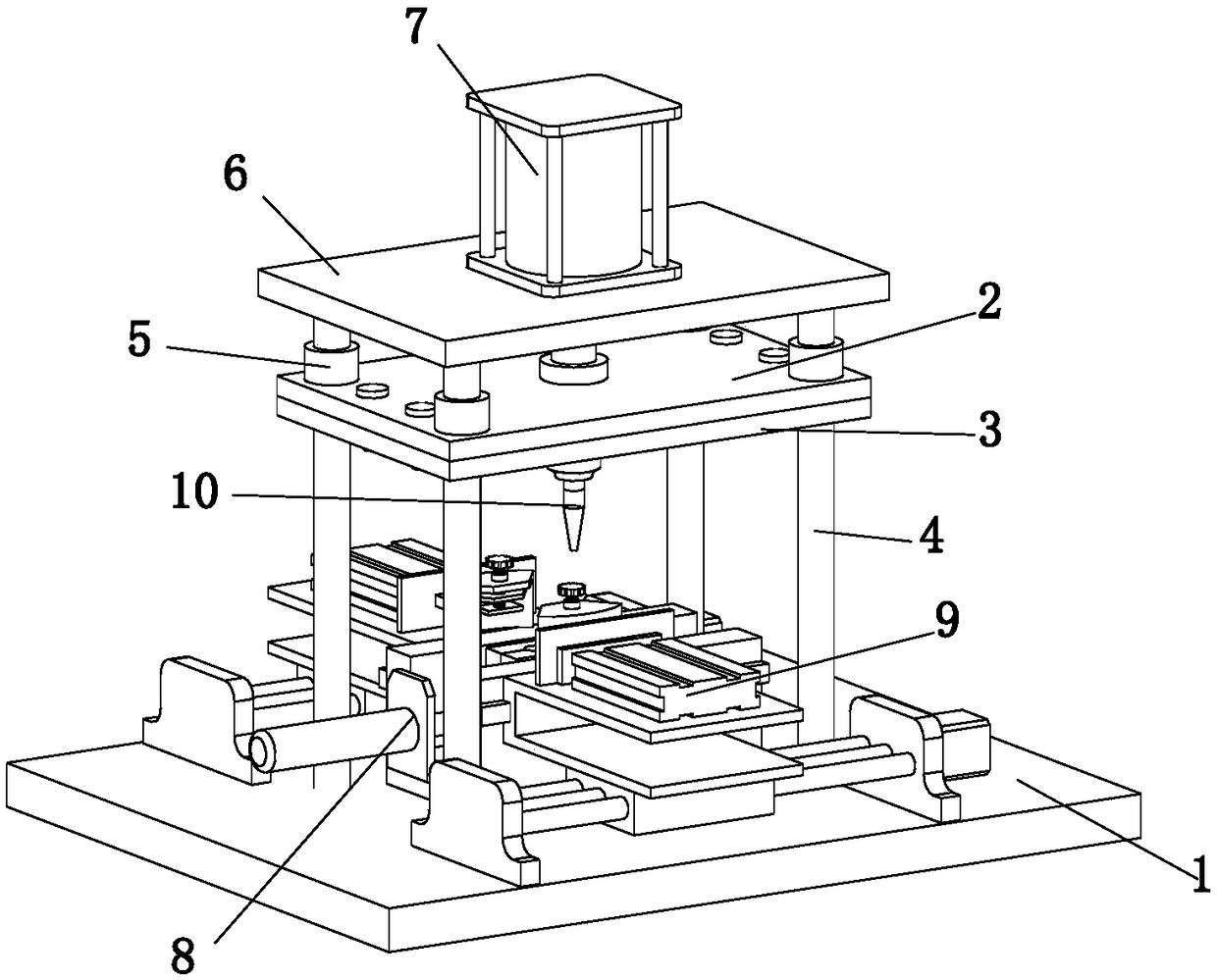
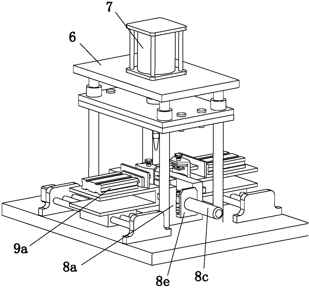
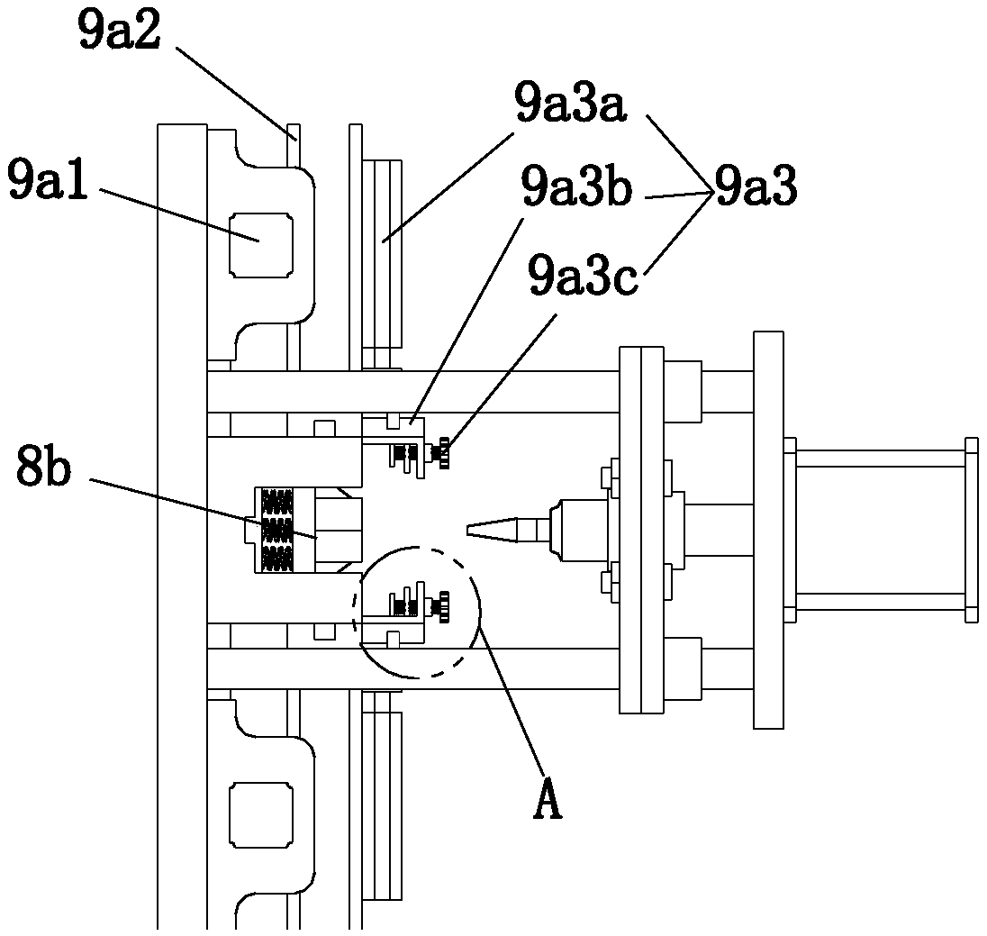
[0026] The following will be combined with Figure 1 to Figure 7 The present invention is described in detail, and the technical solutions in the embodiments of the present invention are clearly and completely described. Apparently, the described embodiments are only some of the embodiments of the present invention, not all of them. Based on the embodiments of the present invention, all other embodiments obtained by persons of ordinary skill in the art without making creative efforts belong to the protection scope of the present invention.

[0027] The present invention provides a kind of high-precision stamping mold that is convenient to replace here by improving, as Figure 1-Figure 7 As shown, it includes a base plate 1 arranged horizontally, an upper formwork 2 and a lower formwork 3 arranged parallel to it directly above the base plate 1, the upper formwork 2 and the lower formwork 3 are fixedly connected by bolts, and the top of the base plate 1 is provided with four Ve...


PUM


Abstract

The present invention relates to the field of dies, in particular to a working method of a high-precision stamping die which is easy to replace, the die comprises a base plate arranged horizontally, an upper template and a lower template arranged in parallel with the base plate are arranged directly above the base plate, the upper template and the lower template are fixedly connected by bolts, four vertically arranged guide columns which are in rectangular arrangement are arranged on the top of the base plate, the upper template and the lower template slidably sleeve the four guide columns, the top of the upper template is provided with four guide sleeves which are slidably fitted with the four guide columns, a load-bearing plate in parallel with the upper template is arranged above the upper template, the two ends of each guide column are fixedly connected with the base plate and the bearing plate respectively, the top of the bearing plate is provided with a press, the top of the baseplate is provided with an adjusting limiting device for carrying the part to be stamped and a positioning device for positioning the part to be stamped, and the bottom of the lower template is provided with a stamping device. The invention has the advantages of simple structure and high stamping precision, the punching requirements of different stamping parts can be satisfied, the working efficiency is improved and strong practicability is realized.

Description

technical field [0001] The invention relates to the field of molds, in particular to a working method of a high-precision stamping mold that is easy to replace. Background technique [0002] Stamping die is a special process equipment for processing materials into parts in cold stamping processing, called cold stamping die, stamping is at room temperature, using the mold installed on the press to apply pressure to the material to make it separate or Plastic deformation, so as to obtain a press processing method for the required parts. During the working process of the stamping die, different dies are often replaced for stamping due to the structure of the stamping part and the stamping production requirements, but the existing devices are often not able to quickly It is better to replace it, especially the existing stamping dies have low positioning accuracy for some stamping parts of the opposite sex (such as stamping parts of the opposite sex in the shape of a ring or a tr...

Claims


Application Information

Patent Timeline
IPC IPC(8): B21D22/02B21D43/00B21D37/04B21D37/10
CPCB21D22/02B21D37/04B21D37/10B21D43/003
Inventor 袁福德杨帆姚政
Owner 中山市祥亿精密五金模具制品有限公司
Why Eureka
Eureka Blog
Learn More