A concealed charging pile mounting structure

A technology of installation structure and charging pile, which is applied to the support structure of photovoltaic modules, electric traction, electric vehicles, etc., can solve problems such as easy to run, energy consumption, and inability to collect solar energy, and achieve simple structure, energy saving, and convenient use Effect

Inactive Publication Date: 2018-12-28
安徽卓越节能科技有限公司
View PDF1 Cites 3 Cited by
  • Summary
  • Abstract
  • Description
  • Claims
  • Application Information

AI Technical Summary

Problems solved by technology

[0003] Most of the current charging piles are exposed to the outside, so they are easy to damage
For this reason, the Chinese patent (authorization announcement: CN207747777U) discloses a lifting type new energy vehicle charging pile. Although the device can prevent cars from being parked indiscriminately, the device cannot collect solar energy when in use and consumes more energy.

Method used


Image

  • A concealed charging pile mounting structure
  • A concealed charging pile mounting structure
  • A concealed charging pile mounting structure

Examples


Embodiment 1

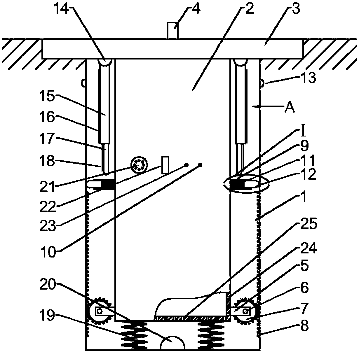
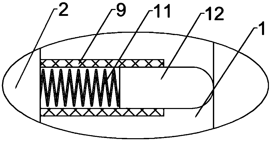
[0022] Example 1: Please refer to figure 1 , a hidden charging pile installation structure, including a charging pile body 2, the charging pile body 2 is located on the installation hole 1 opened below the parking space, the top of the charging pile body 2 is fixedly connected with a barrier plate 3, the barrier plate 3 It is flush with the ground, and the bottom of the charging pile body 2 is symmetrically fixedly connected with a bearing frame 5, and the outer side of the bearing frame 5 is fixedly connected with a fixed shaft 6, and the front and rear ends of the fixed shaft 6 are respectively fixedly connected with a guide gear 7, so The inner wall of the above-mentioned installation hole 1 is symmetrically fixedly connected with guide teeth 8, and the guide teeth 8 mesh with the guide gear 7;

[0023] When installing, dig an installation hole 1 under the parking space, and then install it according to the structure shown in the figure. When the vehicle needs to be charged...

Embodiment 2

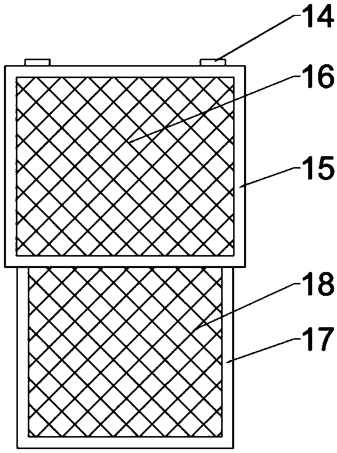
[0034] Example 2: Please refer to image 3 The difference between this embodiment and the previous embodiment is that the left and right sides of the baffle plate 3 are symmetrically fixedly connected to the limit hinge 14, and the guide sleeve plate 15 is fixedly connected to the bottom of the limit hinge 14, and the outside of the guide sleeve plate 15 is fixedly connected. There is a first solar panel 16, the inner side of the guide sleeve 15 is slidably connected with a telescopic energy-collecting panel 17, and the outer side of the telescopic energy-collecting panel 17 is fixedly connected with a second solar panel 18, and the first solar panel 16 and the second solar panel 18 are respectively Electrically connected to the charging pile body 2;

[0035] In this embodiment, the limiting hinge 14 can be rotated outward during charging, and the rotation of the limiting hinge 14 drives the guide cover plate 15 to move outward, and the guide cover plate 15 moves outward to dr...


PUM


Abstract

A concealed charging pile mounting structure in accordance with that present invention, include a charging pile body, A main body of that char pile is arranged on the mount hole arranged under the parking space, At that top of the char pile body is fixedly connected with a shield plate, At that bottom of the char pile body, a bearing frame is symmetrically and fixedly connected with the ground, afixed rotate shaft is fixedly connected with the outside of the bearing frame, guide gears are fixedly connected with the front and rear ends of the fixed rotating shaft respectively, and guide teethare fixedly and symmetrically connected with the left and right inner walls of the mounting holes, and the guide teeth are meshed with the guide gears. In accordance with that prior art, the inventionhas the advantages that: The invention has the advantages of simple structure and convenient use, and can realize the concealed installation of the charging pile by moving the charging pile up and down under the parking space when in use, thus avoiding the situation that the charging pile is installed near the parking space and damaged when reversing, and the device can collect solar energy through the installed solar panel, thereby saving energy.

Description

technical field [0001] The invention relates to the field of charging piles, in particular to a hidden charging pile installation structure. Background technique [0002] The function of the charging pile is similar to that of the fuel dispenser in the gas station. It can be fixed on the ground or on the wall, and installed in public buildings (public buildings, shopping malls, public parking lots, etc.) and residential area parking lots or charging stations. Charge all models of electric vehicles. The input end of the charging pile is directly connected to the AC grid, and the output end is equipped with a charging plug for charging the electric vehicle. Charging piles generally provide two charging methods: conventional charging and fast charging. People can use a specific charging card to swipe the card on the human-computer interaction interface provided by the charging pile to perform corresponding charging methods, charging time, and cost data printing. The display s...

Claims


Application Information

Patent Timeline
Patent Type & Authority Applications(China)
IPC IPC(8): B60L11/18H02S20/30H02S40/36
CPCH02S20/30H02S40/36Y02E10/50
Inventor 王连明周星星王有锁
Owner 安徽卓越节能科技有限公司
Why Eureka
Try Eureka