
a sucker

A suction cup and disc body technology is applied in the field of washing and sweeping vehicles, which can solve the problems of unclean garbage suction, affecting the effect of garbage suction, affecting the washing effect of washing vehicles, etc., so as to improve the cleaning effect and the cleaning effect. Effect

Active Publication Date: 2020-01-21
JINGSU YUEDA SPECIAL VEHICLE CO LTD
View PDF5 Cites 0 Cited by
  • Summary
  • Abstract
  • Description
  • Claims
  • Application Information

AI Technical Summary

Problems solved by technology

Since the right side of the left vacuum hood is adjacent to the left side of the right vacuum hood, there is a suction dead angle, which makes it difficult to pick up garbage, which affects the garbage collection effect.
During the process of picking up garbage in the above-mentioned dust collection room, because the dust is accumulated on the road surface, it is difficult for the dust to be completely sucked into the dust collection room, thereby affecting the cleaning effect of the sweeper.

Method used


Image

  • a sucker
  • a sucker
  • a sucker

Examples


Embodiment Construction

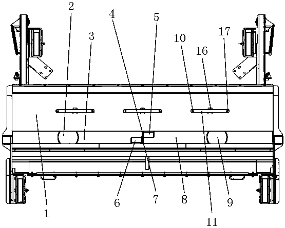
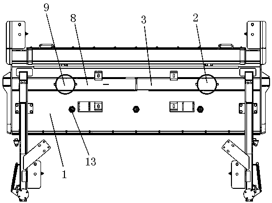
[0013] Figure 1-4 Among them, the present invention discloses a suction cup, which includes a disk body 1, a vacuum chamber, a swing-out high-pressure water spray frame, a high-pressure water spray system and rollers. The dust collection room, the swing-out high-pressure water spray frame, the high-pressure water spray system and the rollers are all arranged on the disc body 1 . The dust chamber is positioned at the middle part of the disk body 1, and the dust chamber includes a left dust chamber and a right dust chamber. The left dust suction chamber comprises a left dust suction hood 3 and a left dust suction pipe 2 , and the left dust suction pipe 2 is arranged on the left dust suction hood 3 . The right dust suction chamber comprises a right dust suction hood 8 and a right dust suction pipe 9, and the right dust suction pipe 9 is arranged on the right dust suction hood 8. The left dust suction cover 3 and the right dust suction cover 8 are respectively located at the le...


PUM


Abstract

A suction disk comprise a disk body, a dust suction chamber, an externally arrange high-pressure water spraying rack, a high-pressure water spraying system and a roller. That right side surface of theleft dust suction cover is provided with a right side cavity cover, the right side cavity cover is located on the right side surface of the left dust suction cover, and the right side cavity cover iscommunicated with the left dust suction cover. A left hollow cavity cover is arranged on that left side surface of the right dust suction cover, the left hollow cavity cover is located on the left side of the left side surface of the right dust suction cover, and the left hollow cavity cover is communicated with the right dust suction cover; And a high-pressure nozzle assembly, comprising a waterspraying pipe, a nozzle and a rotary connecting device, wherein the rotary connecting device comprises a pipe joint, a bearing, a spring, a valve core and a connecting head, wherein a screw hole is arranged in the middle of the water spraying pipe, and an external thread arranged on the outer surface of the lower circular cone structure of the connecting head is arranged on the screw hole arranged in the middle of the water spraying pipe; The pipe joint of the rotary connecting device is arranged on the disk body of the suction disk and is located at the front part of the dust collection chamber. The pipe joint of the rotary connecting device is arranged on the disk body of the suction disk and is located at the front part of the dust collection chamber.

Description

technical field [0001] The invention relates to a sweeper, in particular to a suction cup for a sweeper. Background technique [0002] An existing cleaning and sweeping vehicle contains a suction cup. The suction cup is composed of a disc body, a dust chamber, a swing-out high-pressure water spray frame, a high-pressure water spray system and rollers. The dust collection chamber, the swing-out high-pressure water spray frame, the high-pressure water spray system and the rollers are all arranged on the disc body. The function of the dust collection room is to pick up the garbage and sewage on the road surface. The high-pressure nozzle assembly is located at the rear of the vacuum chamber, and its function is to flush the cleaned road surface, and the roller is for support and movement. The dust collection chamber is positioned at the middle part of the disk body. The dust collection chamber includes a left dust collection chamber and a right dust collection chamber. The le...

Claims


Application Information

Patent Timeline
Patent Type & Authority Patents(China)
IPC IPC(8): E01H1/08E01H1/10
CPCE01H1/0836E01H1/103
Inventor 李婷沈卫琴王涤成孙洪良
Owner JINGSU YUEDA SPECIAL VEHICLE CO LTD
Learn More