Electromagnetic oven with heat dissipation device

A heat dissipation device and induction cooker technology, which is applied in the field of induction cooker, can solve the problems of no discovery, trouble, breakage of the connection between the induction cooker body and the power line, etc., and achieve the effect of reducing loss rate and reducing oil fume pollution

Inactive Publication Date: 2018-12-28
吴联凯
View PDF7 Cites 0 Cited by
  • Summary
  • Abstract
  • Description
  • Claims
  • Application Information

AI Technical Summary

Problems solved by technology

As we all know, people in our country mostly use cooking methods such as steaming, boiling, frying, and frying, which cause very serious kitchen fumes. The heat dissipation structure of induction cookers is similar to that of computers, especially notebooks, but the working environment of computers or notebooks is not in the fumes. environment, this will cause more soot and oil stains to be deposited inside the induction cooker, which will seriously affect the work of the induction cooker over a long period of time. In addition, the inventor also found that the external power cord of the induction cooker is usually directly connected to a section of wire. Because the induction cooker is convenient to store, people usually store it after use, which causes the connection between the induction cooker body and the power cord to break due to winding. Although this kind of repair is not difficult, it causes a lot of trouble , it is also very necessary to design a quick disassembly joint for this purpose
In addition, the inventor of the present invention has also searched for public information provided by the State Intellectual Property Office http: / / www.pss-system.gov.cn / A search was performed on , but no particularly relevant prior art was found

Method used


Image

  • Electromagnetic oven with heat dissipation device
  • Electromagnetic oven with heat dissipation device
  • Electromagnetic oven with heat dissipation device

Examples


Embodiment Construction

[0022] The specific implementation manners of the present invention will be described in further detail below in conjunction with the accompanying drawings.

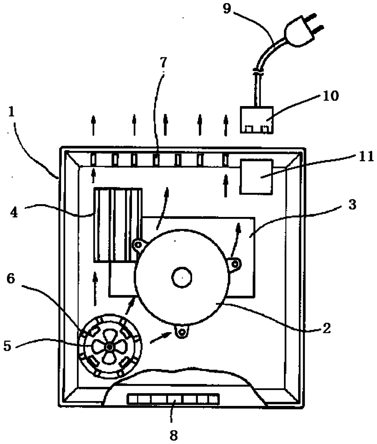
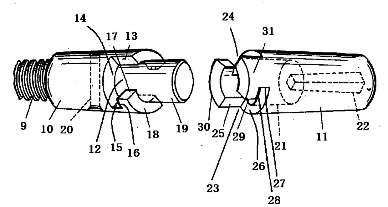
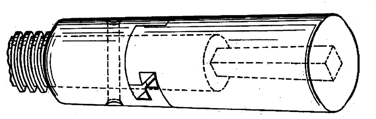
[0023] As shown in the figure, an induction cooker 1 with a heat dissipation device includes a heating element 2, a heating element mounting plate 3, a heat dissipation metal fin plate 4, a main air intake fan 5, a sub-intake module 6, a heat dissipation air outlet 7, and an operation panel 8. Power cord 9, detachable module 10, fixed module 11;

[0024]The detachable module 10 is a hollow cylinder, the left end is connected to the power cord 9, and the right end of the detachable module 10 is provided with a first groove 12 and a second groove along the circumferential direction (not shown in the figure, but the technical field The skilled person can understand), described first groove 12 has first groove first horizontal surface 13, first groove first vertical surface 14, first groove second horizontal surface 15, firs...


PUM


Abstract

The invention relates to an electromagnetic oven with a heat dissipation device. The electromagnetic oven comprises a heating element, a heating element mounting plate, a heat dissipation metal fin plate, a main air inlet fan, a branch air inlet module, heat dissipation air outlets, an operating panel, a power line, a detachable module and a fixing module. Oil smoke pollution to the internal components of the electromagnetic oven is lowered, and meanwhile the loss rate of the power line is decreased in a power line detachable mode.

Description

technical field [0001] The invention relates to an electromagnetic cooker, in particular to an electromagnetic cooker with a novel cooling device. Background technique [0002] Induction cooker is also called induction cooker. The principle of induction cooker is magnetic field induction eddy current heating. It is also the case that the temperature inside the induction cooker will be relatively high. If the heat is not dissipated in time, the internal circuit board will be burned. The utility model whose patent number is CN201620968711.2 provides a high-efficiency heat dissipation induction cooker, which includes a lower shell, a fan, an electromagnetic coil and a circuit board. The circuit board is provided with heating elements, and the lower shell is provided with An air duct and an air guide plate located in the air duct, the fan and the heating element are respectively located at both ends of the air duct, the electromagnetic coil is arranged in the air duct, and the ...

Claims


Application Information

Patent Timeline
Patent Type & Authority Applications(China)
IPC IPC(8): F24C7/00F24C7/08
CPCF24C7/002F24C7/081
Inventor 吴联凯
Owner 吴联凯
Why Eureka
Try Eureka