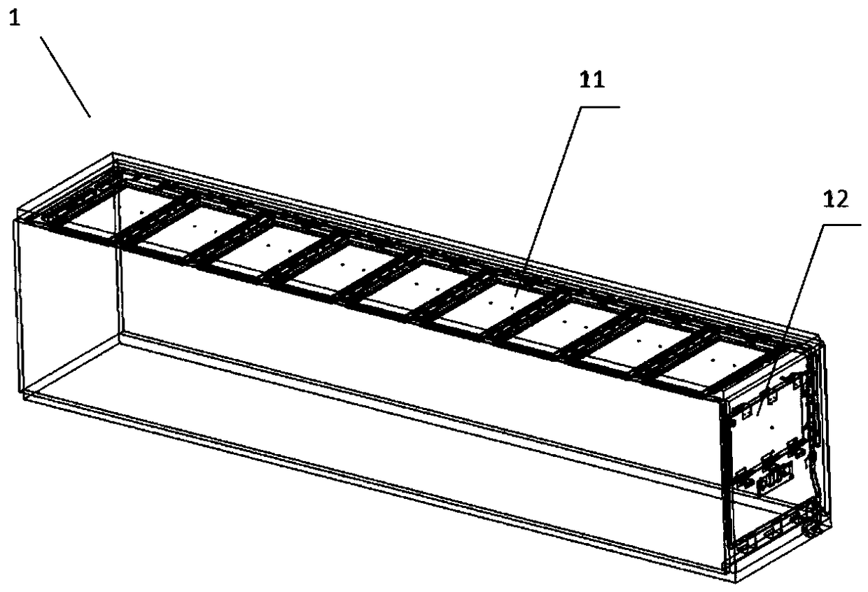
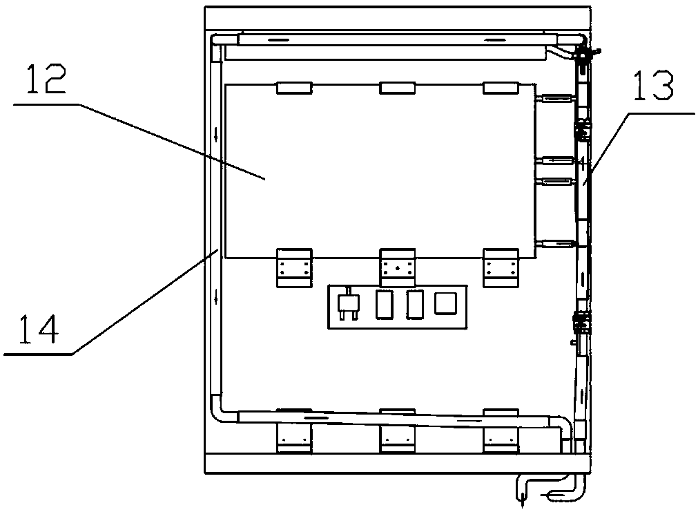
Energy storage unit

A technology of energy storage unit and heat exchange unit, which is applied in coolers, refrigerated cargo transportation, containers, etc. It can solve the problems of poor cold storage effect of phase change materials and achieve rapid cold storage effect

Inactive Publication Date: 2018-12-28
CRRC SHIJIAZHUANG CO LTD +1
View PDF8 Cites 9 Cited by
  • Summary
  • Abstract
  • Description
  • Claims
  • Application Information

AI Technical Summary

Problems solved by technology

However, the cold storage effect of the phase change material of the energy storage device of this patent is relatively poor

Method used


Image

  • Energy storage unit
  • Energy storage unit
  • Energy storage unit

Examples


Embodiment 1

[0052] In Embodiment 1, each heat exchange strengthening unit includes three types of heat exchange fins: first fins 11211, second fins 11212, and third fins 11213, and the fins are arranged to extend radially outward from the tube portion. Linear or arc-shaped fins, the fins extending over the entire axial length of the tube sections, adjacent fins of adjacent tube sections are at least partially thermally conductively connected to each other. The first fins 11211 extend in the adjoining direction X of the tubes, and the second fins 11212 extend in a direction perpendicular to the abutting direction X of the tubes, including directions between the abutting direction of the tubes and the perpendicular direction of the abutting direction A third fin 11213 extends upward. The fins are arranged around the tube, and viewed from any radial section of the tube, the fins form a sunflower pattern around the tube. Each tube part includes two second fins 11212 , and the second fins 112...


PUM


Abstract

The invention provides an energy storage unit. The energy storage unit comprises a shell body (111), a phase change material and a heat exchanger (112). The interior of the shell body (111) limits thespace for accommodating the phase change material. The heat exchanger (112) is arranged for heat exchange with the phase change material, and the heat exchanger (112) includes at least one set of heat transfer units. The cross sections of the heat transfer units include circular portions (1122) and a plurality of scattering lines (1121) around the circular portions. The energy storage unit with the heat transfer units speeds up the cold storage process of the internal phase change material of the energy storage unit, and can realize the rapid cooling of the energy storage unit.

Description

technical field [0001] The invention relates to a cold chain transportation system, in particular to an energy storage unit capable of providing cold energy for storage and transportation devices. Background technique [0002] Fresh products such as vegetables and fruits, processed foods such as quick-frozen foods and dairy products, and various injections, medicines, vaccines and other pharmaceuticals should always be under the specified temperature environment during production, storage, transportation, sales, and consumption. The storage and transportation of these items must rely on special equipment. With the different types of transported items, the temperature maintained in the special equipment is different. The temperature range that refrigerated transport equipment can provide is -18°C to -22°C, the temperature range that refrigerated transport equipment can provide is 0°C to 7°C, and the temperature range that constant temperature transport equipment can provide i...

Claims


Application Information

Patent Timeline
Patent Type & Authority Applications(China)
IPC IPC(8): F28D20/02B65D90/00B60P3/20B60H1/32F25D11/00F25D13/00
CPCB60H1/3201B60P3/20B65D90/00F25D11/00F25D13/00F28D20/02Y02E60/14
Inventor 孟娣丁玉龙聂彬剑张贝王蒙
Owner CRRC SHIJIAZHUANG CO LTD
Why Eureka
Try Eureka