Laser opposite shooting grain flow monitor experimental platform device and control method

A grain flow, laser beam-to-beam technology, applied in measurement devices, test/calibration devices, liquid/fluid solid measurement, etc., can solve the problems of unexperimented grain recycling, low measurement accuracy, and cumbersome test process.

Pending Publication Date: 2018-12-28
JIANGSU UNIV
View PDF2 Cites 0 Cited by
  • Summary
  • Abstract
  • Description
  • Claims
  • Application Information

AI Technical Summary

Problems solved by technology

[0003] Through the retrieval of technical literature, it is found that a grain flow sensor test bench (patent number: 201110140962.3) has a relatively complete test bench structure, which basically reproduces the lifting system on the harvester, but it does not test the circulation of grain in the test bench Utilization requires artificial continuous addition of grains, the test process is cumbersome, and labor costs are increased at the same time
Although the design structure adopted by a grain flow detection test bench (patent number: 201510862561.7) solves the problem of artificial continuous grain addition, its design is not suitable for the calibration of laser through-beam flow sensors
Moreover, none of the existing grain detection test benches has the function of adjusting the angle of the elevator, so it is impossible to study the influence of the change of the angle of the elevator on the flow detection, and it is impossible to determine the best installation position and angle of the flow sensor, and the measurement accuracy is not high. poor reliability

Method used


Image

  • Laser opposite shooting grain flow monitor experimental platform device and control method
  • Laser opposite shooting grain flow monitor experimental platform device and control method
  • Laser opposite shooting grain flow monitor experimental platform device and control method

Examples


Embodiment Construction

[0044] The present invention will be further described below in conjunction with accompanying drawing.

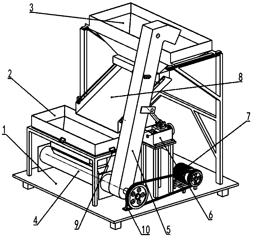
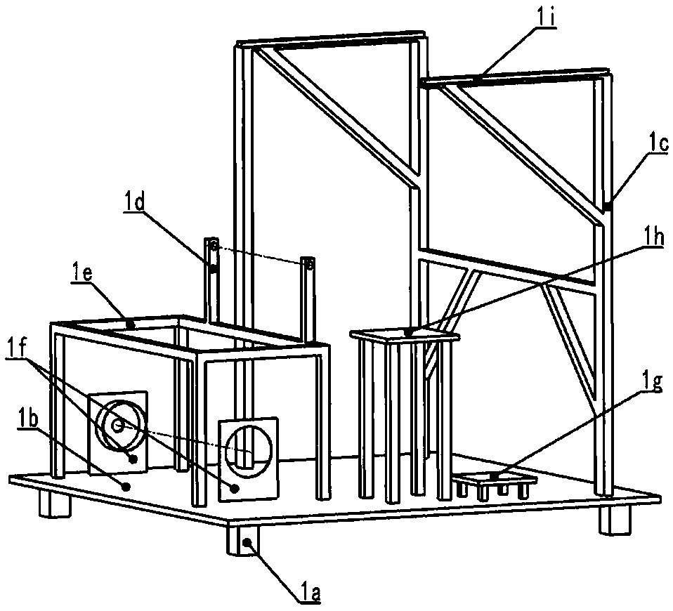
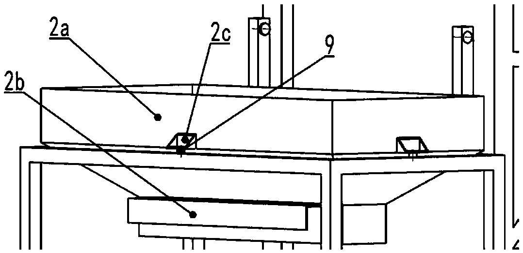
[0045] Such as Figure 1-Figure 10 As shown, the experimental bench device proposed by the present invention includes a frame 1, a grain input box 2, an adjustable grain output box 3, a feed auger mechanism 4, an elevator 5, an elevator angle adjustment mechanism 6, and a load cell 9. The adjustable grain output slideway 8 and the power mechanism 7, wherein the adjustable grain output 3 boxes are installed on the adjustable grain output tank support frame 1c, and the grain output port of the grain output box is connected to the grain output slideway through a pin 8. The lower end of the grain output slideway 8 is fixed by the grain output slideway bracket 1d, and the grain input box 2 is installed above the load cell 9 of the grain input box support frame 1e; the feed auger mechanism 4 is located at the grain output box Right below the opening, it is fixed on the frame 1 t...


PUM


Abstract

The invention discloses a laser opposite shooting grain flow monitor experimental platform device and a control method. The laser opposite shooting grain flow monitor experimental platform device comprises a rack, a grain box, an adjustable grain discharge box, a grain discharge slide way, a feeding auger mechanism, a lifting device, a lifting device angle regulating mechanism, and a power mechanism, wherein the adjustable grain discharge box is arranged at the uppermost position of the rack, the grain box is above the auger, grain falls under gravity from the grain discharge box, enters the grain box through the grain discharge slide way, and then falls into the auger through the grain box, the grain enters the lifting device under push of the auger, then is lifted through a scraper in the lifting device, in lifting, the grain passes a laser opposite shooting flow sensor and is thrown out from a grain discharge port of the lifting device finally, and a weighing sensor at the bottom ofthe grain box weighs reduced grain so as to calibrate the flow sensor. Through adoption of the device, grain is reused in the test platform, when the grain needs to replace, the direction of the grain discharge slide way is regulated, the grain is released and stops being reused. The angle of the lifting device can be regulated, and technical support is provided for determination of an optimal inclination angle of the lifting device.

Description

technical field [0001] The invention relates to the field of agricultural intelligent harvesting equipment, in particular to a grain flow sensor monitoring experiment platform device and a control method. Background technique [0002] When the grain harvester is working in the field, it monitors the yield in real time, which can directly reflect the impact of farmland information on grain growth and yield. After the grain harvest is completed, the yield map can be generated, which can directly help farmers understand the yield information and provide information for the next planting. Information guidance, so as to achieve the operation requirements of precision agriculture. Therefore, the accurate detection of crop yield in the field by the grain flow sensor is a key factor to complete the yield map. At present, there are three main types of grain flow sensors: impact flow sensors, gamma ray flow sensors and photoelectric volumetric flow sensors. In order to better realiz...

Claims


Application Information

Patent Timeline
IPC IPC(8): G01F25/00
CPCG01F25/00
Inventor 陈进韦运余练毅韩帅军
Owner JIANGSU UNIV
Why Eureka
Try Eureka