Wing box microgroove heat pipe heat collecting plate, composed shutter flat-plate solar heat collector and application

A heat collecting plate and heat collector technology, applied in solar heat collectors, solar heat collectors using working fluid, solar thermal energy, etc. Problems such as large thermal resistance, to achieve the effect of simplifying the manufacturing process, improving heat collection efficiency, and reducing production costs

Inactive Publication Date: 2021-01-29
LANZHOU JIAOTONG UNIV
View PDF12 Cites 0 Cited by
  • Summary
  • Abstract
  • Description
  • Claims
  • Application Information

AI Technical Summary

Problems solved by technology

In this kind of heat pipe flat plate heat collector, the heat pipe and the heat absorbing plate are manufactured separately step by step, and then the method of completing the overall assembly of the heat collecting plate elements by welding process has the following disadvantages: first, the welding process requires high requirements, and the manufacturing process is cumbersome and costly. High, difficult, and low efficiency; second, when the heat pipe and the heat-absorbing wing are welded, the welding zone is not completely continuous, which will lead to a large heat transfer resistance of the weld, and its heat collection efficiency is greatly affected by the efficiency of the wing; third, Existing heat pipes and heat collector plates are prone to ablation and penetration when using thin-walled materials for welding connection, resulting in scrapping

Method used


Image

  • Wing box microgroove heat pipe heat collecting plate, composed shutter flat-plate solar heat collector and application
  • Wing box microgroove heat pipe heat collecting plate, composed shutter flat-plate solar heat collector and application
  • Wing box microgroove heat pipe heat collecting plate, composed shutter flat-plate solar heat collector and application

Examples


Embodiment 1

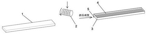
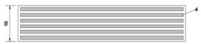
[0032] Embodiment 1, with reference to Figure 4 , a wing box micro-groove heat pipe heat collector plate, copper, aluminum and other metal billets are extruded to form a micro-groove heat pipe box, and then connected with the metal base material of the solar radiation heat absorbing plate as the heat pipe box packaging surface by extrusion It is sealed and molded, and the working fluid vacuum / injection tube reserved on the heat pipe box is evacuated and filled with heat pipe heat exchange fluid to make a wing box micro-groove heat pipe heat collector plate; the surface of the solar radiation heat absorption plate is coated with solar energy selection After absorbing the film, it is used as a heat collector plate for solar radiation light-to-heat conversion, thus forming a wing box micro-groove heat pipe heat collector plate that integrates heat absorption and heat transfer.

[0033] The micro-groove heat pipe of the wing box is divided into an evaporation section, an adiabati...

Embodiment 2

[0041] Embodiment 2, with reference to Figure 9 , a louvered flat-plate solar heat collector composed of wing box micro-groove heat pipe heat collector plates, including a heat exchange heat sink or heat exchange device, and the wing box micro-groove heat pipe solar heat collector plates are used according to the required angle and heat exchange The heat sink or heat exchange device is connected to form a louvered flat solar collector.

[0042] The louver structure of the above-mentioned louvered flat-plate solar collector, which consists of wing box micro-groove heat pipe collector plates as louvers, belongs to the honeycomb structure of the flat-plate collector cover plate. According to the numerical simulation and analysis of the transient thermal performance of the louver-type solar collector It was found that the louvered collector can reduce the heat loss of the collector plate cover by 5% by inhibiting the air convection in the collector cavity.

[0043] The wing box ...

Embodiment 3

[0044] Embodiment 3, the application of a louvered flat solar collector composed of wing box microgroove heat pipe heat collector plates, the louvered flat solar collector can Embedded parts are installed and fixed, or the hanging board on the louver flat solar structure frame is connected and fixed with the building facade structure, and it is easy to arrange vertically on the building facade, replacing the shading, shading, decorative functions of the building's external louvers and building solar heat. Take advantage of the unity of functions.

[0045] Production process of the present invention:

[0046] The core of the present invention is that after the wing box micro-groove heat pipe louver heat collector is made by extrusion process, the required mode louver flat solar collector can be made according to the requirements of use scale, installation conditions and connection device form. details as follows:

[0047] Step 1: Calculate and determine the structural paramet...


PUM


Abstract

The invention provides a wing box microgroove heat pipe heat collecting plate. A metal blank is extruded and formed to form a microgroove heat pipe box, then the microgroove heat pipe box and a solarradiation heat absorbing plate serving as a heat pipe box packaging face are connected in an extrusion manner to form a wing box microgroove heat pipe in a sealed manner, and the wing box microgrooveheat pipe heat collecting plate is manufactured by vacuumizing a working medium vacuum/ injection pipe reserved on the microgroove heat pipe box and filling a heat pipe heat exchange working medium. The surface of the solar radiation heat absorbing plate is coated with a solar selective absorbing film, and therefore the heat collecting and heat transferring integrated function of the wing box microgroove heat pipe heat collecting plate is achieved. The wing box microgroove heat pipe heat collecting plate is connected through bolts, buckles, welding and other methods, and a shutter flat-plate solar heat collector composed of the wing box microgroove heat pipe heat collecting plate is formed. The wing box microgroove heat pipe heat collecting plate is simple in manufacturing process, high inintegration degree, good in anti-freezing performance, modular in structure and flexible and free in assembling, the optimal inclination angle can be used, the building modulus is matched, and good application and popularization prospects are achieved.

Description

technical field [0001] The invention relates to the field of flat solar heat collectors, in particular to a wing box micro-groove heat pipe heat collector plate, a louver flat solar heat collector composed of it and its application. Background technique [0002] As the concept of energy conservation and emission reduction penetrates into people's lives, renewable energy can save traditional resources and reduce pollution. Therefore, the efficient and extensive use of renewable energy such as wind energy and solar energy has become one of the important methods for many industries to achieve energy conservation and emission reduction. In building energy saving and green building design, the purpose of energy saving and emission reduction can be achieved through the application of solar energy and wind energy. Solar energy is the most accessible clean energy, with a large amount and a wide range, and it is easy to be directly developed and utilized. The development of solar en...

Claims


Application Information

Patent Timeline
Patent Type & Authority Applications(China)
IPC IPC(8): F24S10/50F24S10/95F28D15/02
CPCF24S10/50F24S10/95F28D15/02F28D2015/0225Y02B10/20Y02E10/44
Inventor 丁昀杨庆成红娟刘孝敏
Owner LANZHOU JIAOTONG UNIV
Why Eureka
Try Eureka