motor

A stator and strip hole technology, which is used in the manufacture of motor generators, electromechanical devices, electrical components, etc., can solve the problems of reducing the service life of the motor, deformation of the structural parts of the motor, endangering the safety of the motor operation, etc., to improve energy efficiency and preheat. Fast speed and the effect of protecting the motor

Active Publication Date: 2019-05-21
浙江江宇电机有限公司
View PDF5 Cites 0 Cited by
  • Summary
  • Abstract
  • Description
  • Claims
  • Application Information

AI Technical Summary

Problems solved by technology

[0002] At present, in recent years, with the continuous development of the motor industry, motor manufacturers continue to pursue small size and high power density. More and more materials with high electromagnetic load and thermal load are used in motor design, and the loss generated during motor operation increases. The overall temperature rise of the motor is too high or the local temperature rise is too high, which will not only reduce the service life of the motor, affect the efficiency, torque and other economic and technical indicators of the motor, but also cause serious deformation of the structural parts of the motor, endangering the safety of the motor operation
In addition, during the working process of the existing motor, strong vibration will be generated due to the excessive rotation of the rotor, which will lead to unstable operation of the motor and affect the stable operation of the motor

Method used


Image

  • motor
  • motor
  • motor

Examples


Embodiment Construction

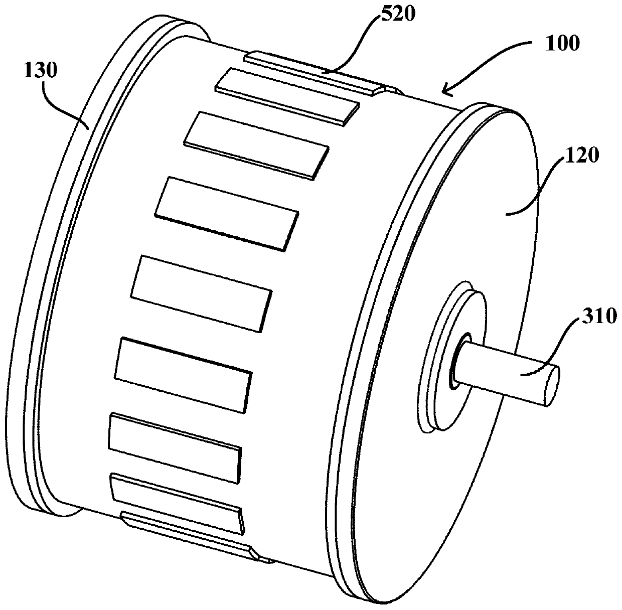
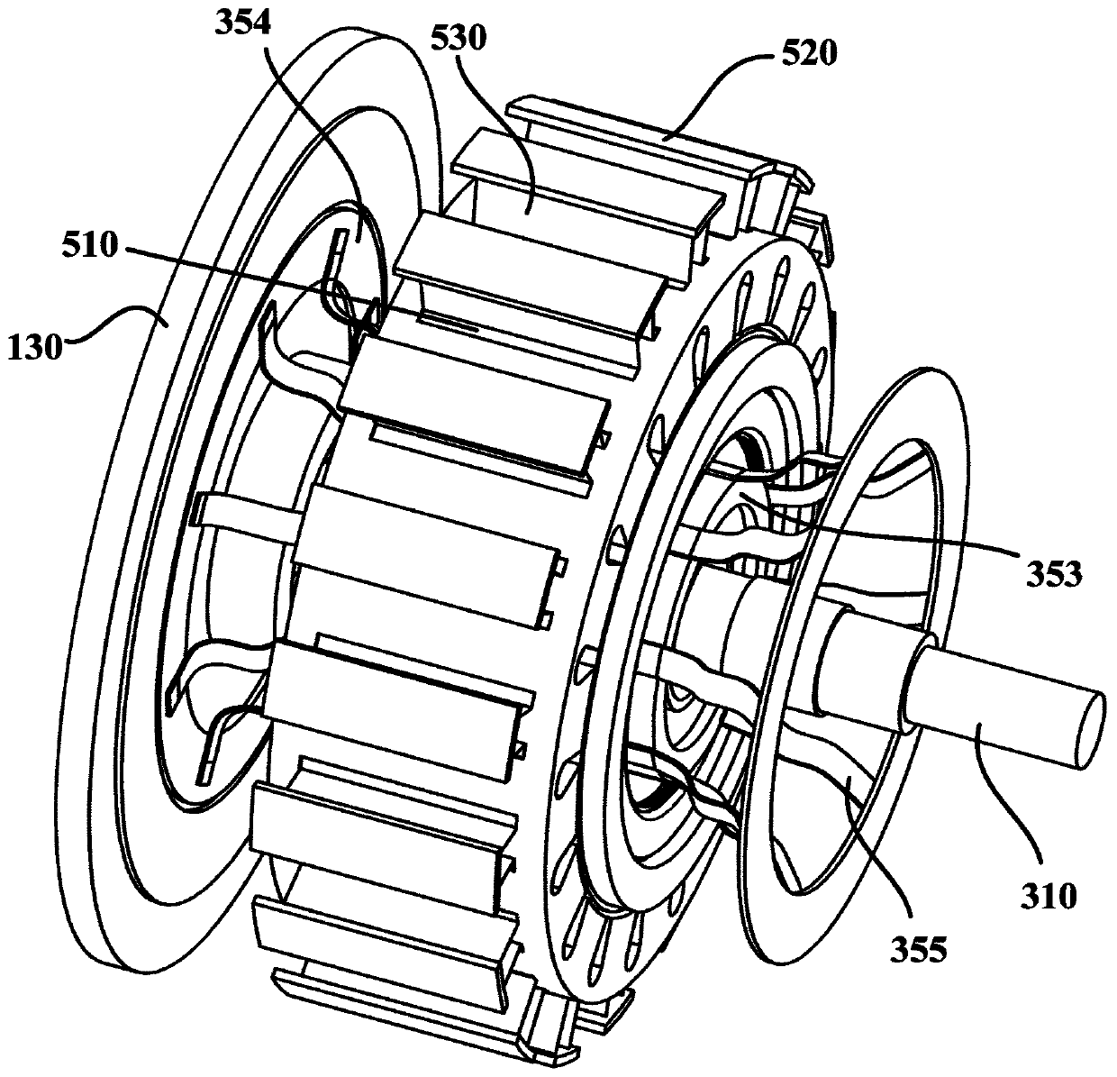
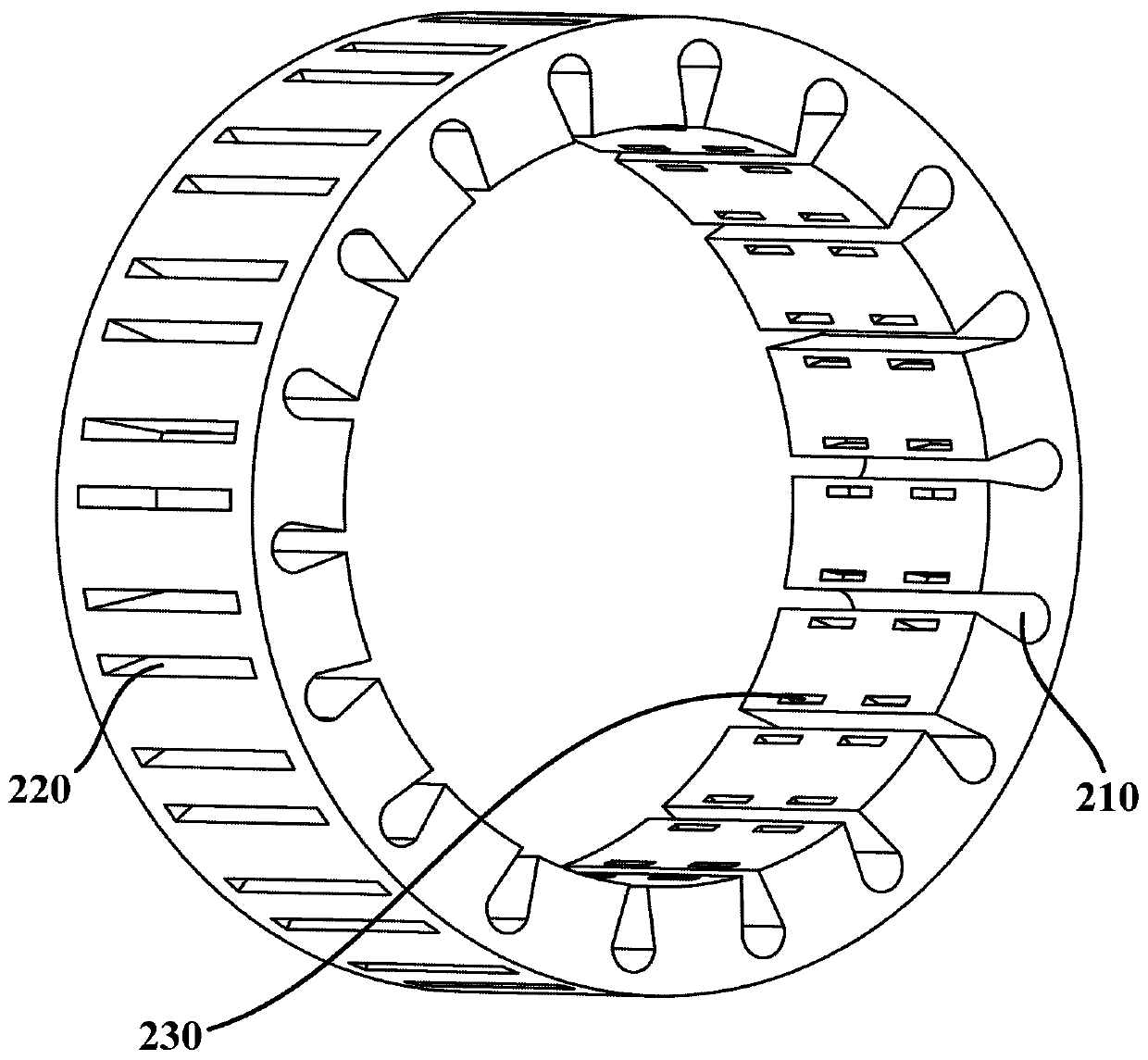
[0042] figure 1 is a schematic structural diagram of a motor according to an embodiment of the present invention. Such as figure 1 shown, and refer to figure 2 and image 3 , the embodiment of the present invention provides a motor. Generally, the motor may include a housing 100 , a stator 200 and a rotor 300 . The housing 100 generally has a main housing 110 and end covers disposed on two ends of the main housing 110 , such as a housing front cover 120 and a housing rear end cover 130 . The stator 200 is disposed in the housing 100 . The rotor 300 is disposed radially inside the stator 200 . The iron core of the stator 200 has stator slots 210 for winding windings 240 .

[0043] In particular, the stator 200 also has a plurality of cooling hole groups, and each cooling hole group has two first strip-shaped holes 220 disposed on both sides of a corresponding stator slot 210 . Each first strip-shaped hole 220 extends along the axial direction of the stator 200 , and op...


PUM


Abstract

A motor is provided. The motor comprises a housing, a stator and a rotor. The stator further has a plurality of heat dissipation hole groups, each heat dissipation hole group having two first strip-shaped holes arranged on both sides of a corresponding stator slot, each first strip-shaped hole extending in an axial direction of the stator and opening toward a radially outer side of the stator; thehousing is provided with a plurality of second strip holes, and each second strip hole corresponding to a first strip hole. The motor further includes a plurality of first semiconductor cooling sheets, each semiconductor cooling sheet being inserted into a first strip-shaped hole, and a cold end face of each semiconductor cooling sheet facing a stator slot adjacent thereto; an outer heat dissipation device is arranged on the outer surface of the housing; a plurality of first heat conduction fins are included, each of which is connected with an external heat dissipation device, and each of thefirst heat conduction fins is inserted into a second strip hole and a corresponding first strip hole, and contacts with a hot end surface of a semiconductor cooling sheets in the first strip hole. The motor has high heat dissipation efficiency and excellent motor performance.

Description

technical field [0001] The invention relates to the field of motors, in particular to a motor with excellent heat dissipation. Background technique [0002] At present, in recent years, with the continuous development of the motor industry, motor manufacturers continue to pursue small size and high power density. More and more materials with high electromagnetic load and thermal load are used in motor design, and the loss generated during motor operation increases. If the overall temperature rise of the motor is too high or the local temperature rise is too high, it will not only reduce the service life of the motor, affect the efficiency, torque and other economic and technical indicators of the motor, but also cause serious deformation of the structural components of the motor, endangering the safety of the motor. In addition, during the working process of the existing motor, the rotor rotates too violently, which will generate strong vibration. The violent vibration will ...

Claims


Application Information

Patent Timeline
Patent Type & Authority Patents(China)
IPC IPC(8): H02K9/00H02K1/20H02K9/22H02K15/12H02K1/12
CPCH02K1/12H02K1/20H02K9/00H02K9/22H02K15/12H02K2213/03
Inventor 尹洁李晓宇尹东升
Owner 浙江江宇电机有限公司
Why Eureka
Try Eureka