
A digital channelized receiver pulse detection system

A technology of digital channelization and pulse detection, applied in transmission systems, electrical components, etc., can solve the problems of waste, autocorrelation detection method multiple multipliers and adder resources, unsatisfactory detection results, etc., to reduce false alarm probability, The effect of saving hardware resources

Inactive Publication Date: 2018-12-28
BEIJING INST OF REMOTE SENSING EQUIP
View PDF3 Cites 3 Cited by
  • Summary
  • Abstract
  • Description
  • Claims
  • Application Information

AI Technical Summary

Problems solved by technology

The time-domain detection method is prone to false alarms, and the detection results are not ideal when the signal-to-noise ratio is low
The frequency domain detection method needs to perform FFT on the output of all channels, which will use a lot of FPGA resources, which is wasteful
The autocorrelation detection method also requires more multiplier and adder resources

Method used


Image

  • A digital channelized receiver pulse detection system

Examples


Embodiment Construction

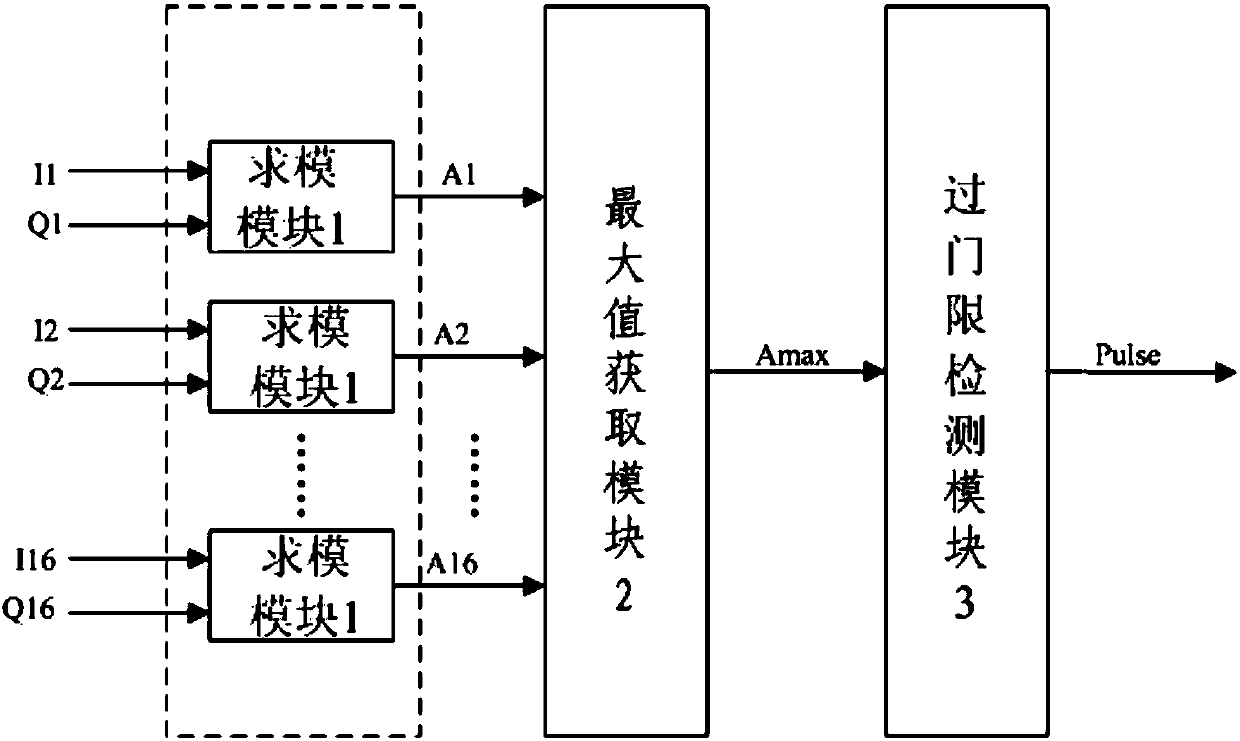
[0011] A pulse detection system for a digital channelized receiver, comprising: a channel and modulo calculation module 1 , a maximum value acquisition module 2 and a threshold crossing detection module 3 . Wherein, the number of modulo modules 1 is equal to the number of channels.

[0012] The input ends of the 16 modulo seeking modules 1 are respectively connected to the I and Q signal output terminals of 16 channels, and the output ends of the 16 modulo seeking modules 1 are all connected to the input ends of the maximum value acquisition module 2, and the maximum value acquisition module The output end of 2 is connected with the input end of threshold crossing detection module 3 .

[0013] When the detection system is working, firstly, the module 1 modulo-calculates the I and Q signals output by the 16 channels to obtain the signal amplitude A of the 16 channels 16 ; Then the amplitude A of each channel acquired by the maximum value acquisition module 2 16 Perform compar...


PUM


Abstract

The invention discloses a digital channelization receiver pulse detection system, comprising: a channel, a module (1) for obtaining a maximum value, a module (2) for obtaining a maximum value, and a threshold detection module (3). Wherein the number of modules (1) is equal to the number of channels, the signal amplitudes of each channel are calculated by using the I and Q signals of n channels, the maximum values of the n signal amplitudes are searched for, the maximum values are compared with a fixed threshold, the signal is judged to be present when the threshold is passed, otherwise no signal is obtained. The invention belongs to the technical field of signal processing. According to the characteristics of the signal, the invention judges whether the signal exists or not by comparing the maximum amplitude value with the threshold value, reduces the false alarm probability, and saves a large amount of hardware resources at the same time.

Description

technical field [0001] The invention relates to a pulse detection system, in particular to a digital channelized receiver pulse detection system. Background technique [0002] The modern electromagnetic signal environment is becoming more and more complex and dense, requiring the electronic warfare receiver to have a wide processing bandwidth, high sensitivity, large dynamic range, multi-signal parallel processing and real-time processing capabilities of a large amount of information. The digital channelized receiver can not only better meet the above requirements, but also realize the full probability interception of signals in the monitoring channel. [0003] After channelization, the data of N channels are output at the same time, and it is unknown which channel the signal is in. Traditional channel detection methods include time domain detection, frequency domain detection and autocorrelation detection. The time-domain detection method is prone to false alarms, and the...

Claims


Application Information

Patent Timeline
IPC IPC(8): H04B1/16
CPCH04B1/1638
Inventor 许家安李冬温顾琴昱张震
Owner BEIJING INST OF REMOTE SENSING EQUIP
Learn More