Automatic lifting electric cook pot

A technology of automatic lifting and electric cooking pots, applied to the utensils with integral electric heating devices, the structure of cooking utensils, plug-ins, etc., can solve the problems of easy aging damage, dirt accumulation, leakage, etc., to avoid pollution of soup, Avoid damage, easy to clean the effect

Pending Publication Date: 2019-01-01
中山市欧莱克电器有限公司
View PDF0 Cites 2 Cited by
  • Summary
  • Abstract
  • Description
  • Claims
  • Application Information

AI Technical Summary

Problems solved by technology

[0002] Most of the current lift-type electric cooking pots use a contact transmission connection between the inner pot and the transmission terminal of the mechanical lifting mechanism. Therefore, an exposed transmission terminal is formed in the bottom pot, resulting in the formation of a sealing device in the b

Method used


Image

  • Automatic lifting electric cook pot
  • Automatic lifting electric cook pot
  • Automatic lifting electric cook pot

Examples


Example Embodiment

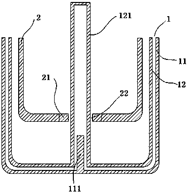
[0040] In one embodiment, the first magnetic device 111 is an electromagnet, and the second magnetic device 21 is a permanent magnet.
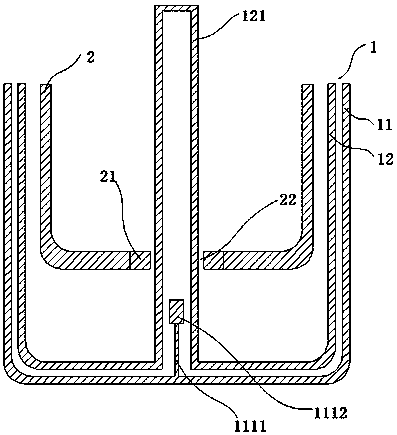
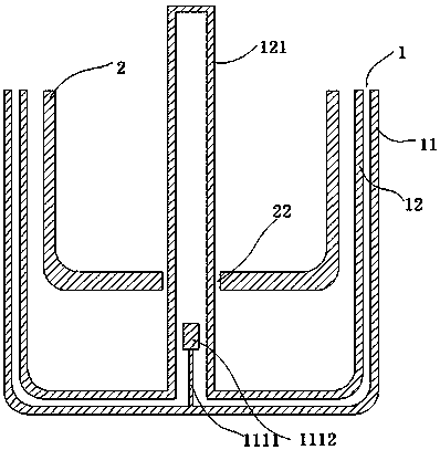
[0041] One of the implementation methods, such as figure 2 The first magnetic device 111 includes a magnetic component 1112 and a driving mechanism 1111 that drives the magnetic component 1112 to reciprocate up and down. The magnetic component 1112 and the second magnetic device 21 are both permanent magnets.

[0042] In one embodiment, the inner pot 2 is an iron pot, and the second magnetic device 21 is the inner pot 2 itself, or the second magnetic device 21 is an iron block.

[0043] One of the implementation methods, such as Figure 4 The sliding tube 121 is a hollow cylindrical tube with a closed upper end.

[0044] In one embodiment, the sliding tube 121 is a hollow square tube with a closed upper end.

[0045] In one embodiment, the sliding tube 121 and the outer pot 1 are integrally formed.

[0046] In one embodiment, the inner pot 2 is provided...


PUM


Abstract

The invention relates to an automatic lifting electric cook pot, which comprises an outer pot, and a first magnetic force device is fixedly arranged at the bottom of the outer pot; an inner pan is arranged inside the outer pan, a second magnetic device is arranged at the bottom of the inner pan, and the second magnetic device can drive the first magnetic device to move up and down by magnetic force. The invention makes the inner pot move up and down inside the outer pot through the action of the magnetic force, avoids the leakage of the lifting device, and at the same time uses the magnetic force to drive the inner pot to move up and down without the complicated mechanical structure, so that the inner pot is convenient to be disassembled and washed.

Description

technical field [0001] The invention relates to the field of electrical appliances, in particular to an automatic lifting electric cooking pot. Background technique [0002] Most of the current lift-type electric cooking pots use a contact transmission connection between the inner pot and the transmission terminal of the mechanical lifting mechanism. Therefore, an exposed transmission terminal is formed in the bottom pot, resulting in the formation of a sealing device in the bottom pot. The sealing device is prone to aging, damage, leakage and accumulation of dirt in a high-temperature and complex working environment, and it is difficult to achieve a separate design for the bottom pan and the main body of the machine, and it is impossible to realize the split cleaning in daily habits. Contents of the invention [0003] Based on this, it is necessary to provide an automatic lifting electric cooking pot, which is characterized in that it includes an outer pot, the bottom of ...

Claims


Application Information

Patent Timeline
IPC IPC(8): A47J27/00A47J36/20
CPCA47J27/002A47J27/004A47J36/20
Inventor 陈宏程
Owner 中山市欧莱克电器有限公司
Why Eureka
Try Eureka