Friction welding equipment

A technology of friction welding and equipment, which is applied in welding equipment, non-electric welding equipment, metal processing equipment, etc., can solve the problems affecting processing efficiency and cumbersomeness, and achieve the effect of convenient operation and simple structure

Inactive Publication Date: 2019-01-01
诸暨市永奇电子科技有限公司
View PDF0 Cites 2 Cited by
  • Summary
  • Abstract
  • Description
  • Claims
  • Application Information

AI Technical Summary

Problems solved by technology

[0002] At present, most friction stir welding machines have a large volume, and the friction welding workpiece is large, which needs to be fixed by rigid connection. After friction stir welding, a small amount of flash will be left on the workpiece. Compared with traditional dismantling of the workpiece, the processing of the flash It is cumbersome and affects the processing efficiency. In addition, the keyhole will be left after the friction stir welding, and the additional filling of the keyhole will also increase the processing procedure. Therefore, a friction welding equipment that can automatically process the flash and keyhole after welding is needed.

Method used


Image

  • Friction welding equipment
  • Friction welding equipment
  • Friction welding equipment

Examples


Embodiment Construction

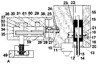
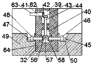
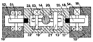
[0012] Combine below Figure 1-3 The present invention will be described in detail.

[0013] refer to Figure 1-3 , according to the friction welding equipment of the embodiment of the present invention, the friction welding main body support 10 is included, the stirring needle 11 is fixedly installed in the bottom end surface of the friction welding main body support 10, and the opening is provided in the friction welding main body support 10 Auxiliary device cavity 12, the auxiliary device cavity 12 is slidingly fitted with an auxiliary welding slide table 13 between the left and right walls, and the auxiliary welding slide table 13 extends downwards through the bottom end surface of the friction welding main body bracket 10. The auxiliary welding slide 13 is provided with a filling feeding chamber 19, the bottom wall of the filling feeding chamber 19 is provided with a feeding chamber 15 with an opening downward, and symmetrical installation teeth are fixed on the left and...


PUM


Abstract

The invention discloses friction welding equipment. The friction welding equipment comprises a friction welding main body bracket, wherein a mixing pin is fixedly installed in the bottom end surface of the friction welding main body bracket, an auxiliary device cavity with an upward opening is formed in the friction welding main body bracket, an auxiliary welding sliding table is installed betweenthe left and right walls of the auxiliary device cavity in a sliding fit mode, the auxiliary welding sliding table extends downwards and penetrates through the bottom end surface of the friction welding main body bracket, a filling feed cavity is formed in the auxiliary welding sliding table, a feed cavity with a downward opening is formed in the bottom wall of the filling feed cavity, racks arefixedly and symmetrically installed on the left and right end surfaces of the auxiliary welding sliding table, a sliding table feed cavity which communicates with the auxiliary device cavity is formedin the left and right walls of the auxiliary device cavity, a first motor is fixedly installed in the back wall of the filling feed cavity, and a driving feed shaft is fixedly connected to the end surface of the front side of a forward output shaft of the first motor.

Description

technical field [0001] The invention relates to the field of friction welding, in particular to friction welding equipment. Background technique [0002] At present, most friction stir welding machines have a large volume, and the friction welding workpiece is large, which needs to be fixed by rigid connection. After friction stir welding, a small amount of flash will be left on the workpiece. The traditional disassembly of the workpiece is compared with the processing of the flash. It is cumbersome and affects the processing efficiency. In addition, the keyhole will be left after friction stir welding, and the additional filling of the keyhole will also increase the processing procedure. Therefore, a friction welding equipment that can automatically process the flash and keyhole after welding is needed. Contents of the invention [0003] The object of the present invention is to provide friction welding equipment for overcoming the above-mentioned defects in the prior art...

Claims


Application Information

Patent Timeline
Patent Type & Authority Applications(China)
IPC IPC(8): B23K20/12B23K20/26
CPCB23K20/12B23K20/1245B23K20/26
Inventor 吴娜
Owner 诸暨市永奇电子科技有限公司
Why Eureka
Try Eureka