Network cabinet production assembly line

A technology for production lines and network cabinets, which is applied in welding equipment, metal processing equipment, spraying devices, etc., can solve the problems of affecting the spraying quality of network cabinets, affecting the appearance and quality of use, and the surface of network cabinets is not smooth, so as to avoid uneven spraying Uniformity, reduce vibration, avoid the effect of loose parts

Inactive Publication Date: 2019-01-01
SHENZHEN HUARONG TECH
View PDF11 Cites 2 Cited by
  • Summary
  • Abstract
  • Description
  • Claims
  • Application Information

AI Technical Summary

Problems solved by technology

[0002] With the development of society, the demand for network cabinets is increasing. As we all know, network cabinets are used to combine installation panels, plug-ins, sub-boxes, electronic components, devices and mechanical parts and components to form a whole installation box. According to the current In terms of types, there are server cabinets, wall-mounted cabinets, network cabinets, standard cabinets, intelligent protective outdoor cabinets, etc. The production line of network cabinets generally needs to go through blanking, welding and molding, and painting lamp processes. However, the existing production lines exist Some disadvantages, firstly, network cabinets of different sizes cannot be fixed during welding, in addition, the existing production line cannot absorb shocks during work, long-term vibration can easily reduce the service life of the device, and when the plastic powder is sprayed on the cabinet, the spraying Unevenness greatly affects the spraying quality of the network cabinet, making the surface of the network cabinet not smooth, affecting the appearance and quality of use

Method used


Image

  • Network cabinet production assembly line
  • Network cabinet production assembly line
  • Network cabinet production assembly line

Examples


Embodiment Construction

[0014] The following will clearly and completely describe the technical solutions in the embodiments of the present invention with reference to the accompanying drawings in the embodiments of the present invention. Obviously, the described embodiments are only some, not all, embodiments of the present invention. Based on the embodiments of the present invention, all other embodiments obtained by persons of ordinary skill in the art without making creative efforts belong to the protection scope of the present invention.

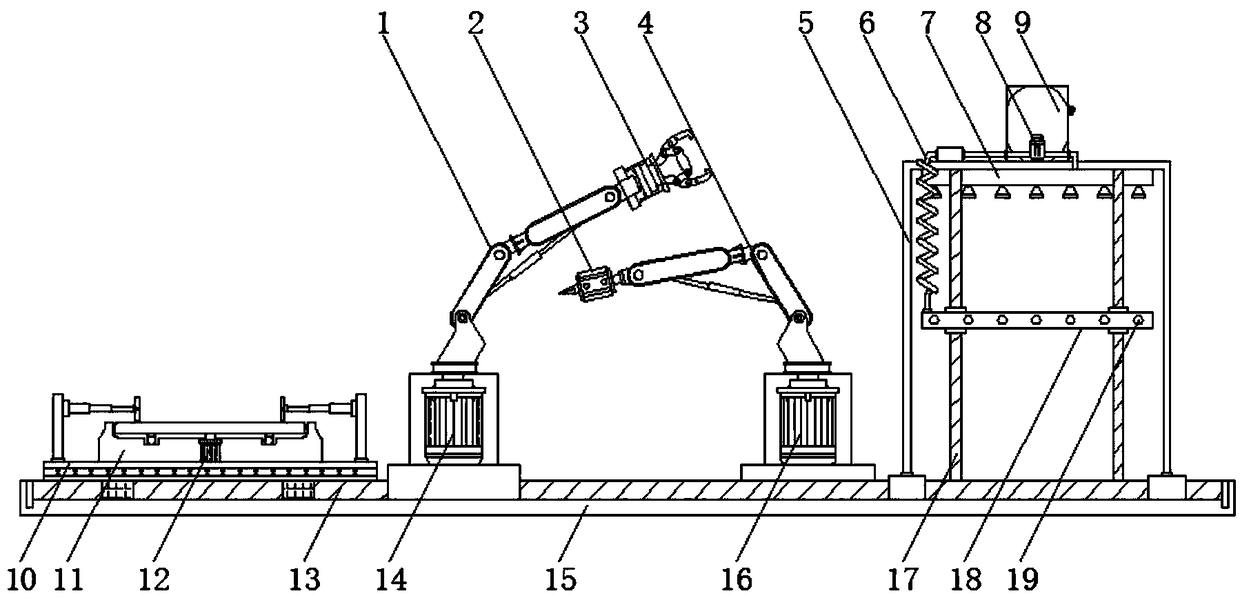
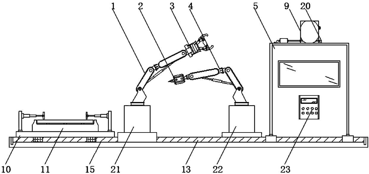
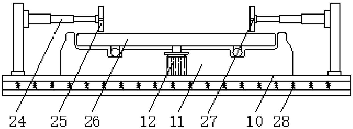
[0015] see Figure 1-3 , an embodiment provided by the present invention: a network cabinet production line, including a frame body 5, a base 10 and a transmission plate 15, both sides of the transmission plate 15 are provided with first electromagnetic slide rails 13, and the first electromagnetic slide rails One end of 13 is equipped with base 10 by slide block, and the inside of base 10 is evenly fixed with shock-absorbing spring 28, is convenient to reduce...


PUM


Abstract

The invention discloses a network cabinet production assembly line which comprises a frame body, a base and a conveying plate, wherein first electromagnetic sliding rails are arranged on both sides ofthe conveying plate; the base is mounted at one end of the first electromagnetic sliding rails through sliding blocks; hydraulic telescopic rods are mounted at both ends of the top of the base through vertical rods; clamping plates are mounted at the ends, far away from the vertical rods, of the hydraulic telescopic rods; pressure sensors are mounted at the inner middle positions of the clampingplates; a supporting seat is mounted at the middle position of the top end of the base; a driving motor is mounted at the inner bottom end of the supporting seat; a workbench is mounted at the top endof the supporting seat; and the output end of the driving motor is connected with the bottom end of the workbench through a rotating shaft. The network cabinet production assembly line disclosed by the invention is equipped with the hydraulic telescopic rods and the clamping plates, so that network cabinets of different specifications can be conveniently fixed when processed, the fixed network cabinets can be prevented from being knocked down due to the action of an external force during the conveying process, and then the network cabinet production efficiency can be improved.

Description

technical field [0001] The invention relates to the technical field of cabinet production, in particular to a network cabinet production line. Background technique [0002] With the development of society, the demand for network cabinets is increasing. As we all know, network cabinets are used to combine installation panels, plug-ins, sub-boxes, electronic components, devices and mechanical parts and components to form a whole installation box. According to the current In terms of types, there are server cabinets, wall-mounted cabinets, network cabinets, standard cabinets, intelligent protective outdoor cabinets, etc. The production line of network cabinets generally needs to go through blanking, welding and molding, and painting lamp processes. However, the existing production lines exist Some disadvantages, firstly, network cabinets of different sizes cannot be fixed during welding, in addition, the existing production line cannot absorb shocks during work, long-term vibra...

Claims


Application Information

Patent Timeline
Patent Type & Authority Applications(China)
IPC IPC(8): B23K31/02B05B13/02
CPCB05B13/0228B05B13/0285B23K31/02
Inventor 尹春生
Owner SHENZHEN HUARONG TECH
Why Eureka
Try Eureka