

Seamless steel pipe clamping mechanism
A technology of clamping mechanism and seamless steel pipe, applied in the direction of auxiliary devices, auxiliary welding equipment, welding/cutting auxiliary equipment, etc., can solve problems such as inability to weld butt joints, unstable clamping, etc., and achieve improved clamping effect and stability sexual effect
- Summary
- Abstract
- Description
- Claims
- Application Information
AI Technical Summary
Problems solved by technology
Method used
Image

Examples
Embodiment 1
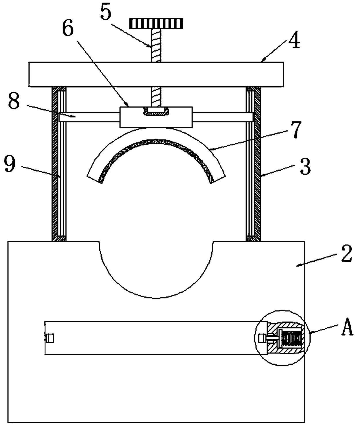
[0028] see figure 2 , the upper end of the support base 2 of the present invention is provided with a first arc-shaped through groove, and the four corners of the upper end of the support base 2 are fixedly connected with support rods 3, and the upper ends of the four support rods 3 are jointly fixedly connected with a support plate 4, and the support plate 4 The center of the upper end is threadedly connected with a screw 5 through a threaded hole, and the lower end of the screw 5 extends to the bottom of the support plate 4 and rotates through the first rolling bearing to be rotatably connected with the lower pressing rod 6, and the lower sides of both ends of the lower pressing rod 6 are fixed. An arc splint 7 is connected, and the upper end of the screw rod 5 is fixedly connected with a first runner.
[0029]To sum up: the seamless steel pipe can be placed through the first arc-shaped through groove arranged on the upper end of the support seat 2, and the screw rod 5 can ...
Embodiment 2
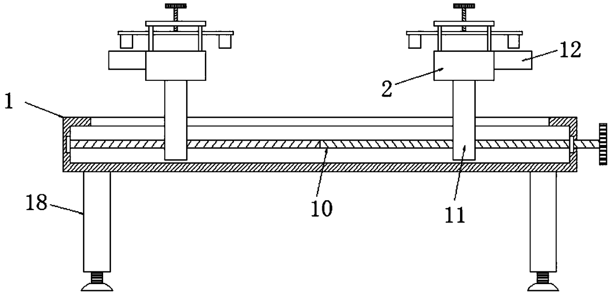
[0031] see figure 1 , the interior of the base 1 of the present invention is provided with a two-way screw 10, both ends of the two-way screw 10 are rotatably connected to the two inner side walls of the base 1 respectively through the second rolling bearing, and one end of the two-way screw 10 runs through the inner side wall of the base 1 side And be fixedly connected with the second runner, the bar wall of bidirectional screw 10 is all vertically threaded and connected with moving rod 11, the upper end of base 1 is provided with strip hole horizontally, the upper end of two moving rods 11 passes through the strip hole and separates It is fixedly connected with the lower ends of the two support bases 2, and the rod walls of the two moving rods 11 are all slidably connected with the inner walls of the bar-shaped holes.
[0032] To sum up: through the second wheel arranged at one end of the two-way screw 10, turning the second wheel drives the two-way screw 10 to rotate, and t...
Embodiment 3
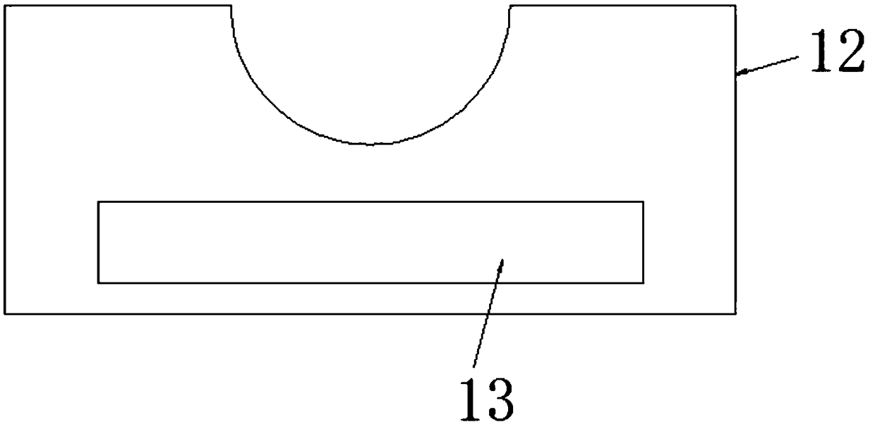
[0034] see image 3 and Figure 4 The upper ends of the two extension boards 12 of the present invention are provided with a second arc-shaped through groove, one side of the two extension boards 12 is fixedly connected with an insert block 13, and the side walls of the two support bases 2 are respectively provided with two The slots that are matched with each plug block 13, the insides of the two support bases 2 are respectively provided with cavities on both sides of the two slots, and the insides of the multiple cavities are all provided with clamps for the plug block 13 to be clamped. mechanism, the clamping mechanism includes an extrusion plate 14 that is vertically slidably connected inside the cavity, one side of the extrusion plate 14 is fixedly connected with a spring 15, and the side of the spring 15 away from the extrusion plate 14 is connected to the side of the cavity. The wall is fixedly connected, and the side of the extrusion plate 14 away from the spring 15 i...
PUM
 Abstract
Description
Claims
Application Information