Polling rail of polling robot applied to pipe rack and pipe rack control system

An inspection robot and track technology, applied in the direction of program control manipulators, manipulators, manufacturing tools, etc., can solve the problems of inspection track blocking function exit, personnel life safety risks, etc.

Pending Publication Date: 2019-01-01
ZHEJIANG GUOZI ROBOT TECH
View PDF9 Cites 6 Cited by
  • Summary
  • Abstract
  • Description
  • Claims
  • Application Information

AI Technical Summary

Problems solved by technology

However, due to the limited environment of the pipe gallery, when the inspection track of the inspection robot is laid, the inspection track blocks the functional exit, which may cause a risk to the safety of personnel

Method used


Image

  • Polling rail of polling robot applied to pipe rack and pipe rack control system
  • Polling rail of polling robot applied to pipe rack and pipe rack control system
  • Polling rail of polling robot applied to pipe rack and pipe rack control system

Examples


Embodiment 1

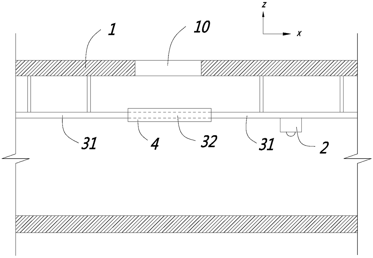
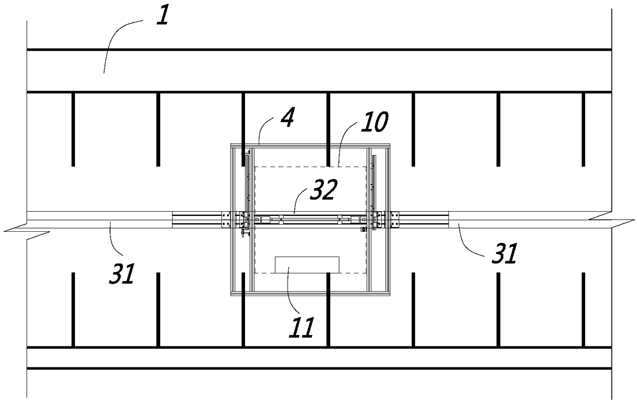
[0037] Such as Figure 1 to Figure 5 As shown, this embodiment is an inspection track of an inspection robot applied in a pipe gallery, and the inspection track is for the inspection robot 2 to walk. In this embodiment, the inspection robot 2 is preferably hung under the inspection track. For the pipe gallery 1, there is a functional exit 10 on the top, and the inspection track is located below the functional exit 10, and the space of the pipe gallery 1 is limited. Generally, the inspection track and the functional exit 10 will overlap, that is, in the horizontal projection The direction inspection track will cross the functional exit 10 of the pipe gallery 1, see figure 2. Functional exit 10 can be used for personnel escape, and can also be used for supplying goods transportation, and described inspection track comprises the main body section track 31 that is positioned at described functional exit 10 both sides and is used for the main body section of described two sides. ...

Embodiment 2

[0053] Such as Figure 6 As shown, the difference between this embodiment and Embodiment 1 is that the switching mechanism 4 of this embodiment is different. The switching mechanism 4 in this embodiment includes a rotating shaft 42, and the movable segment track 32 is relatively to the The rotatable connection of the main body section track 31 is equivalent to changing the sliding mode of the movable section track 32 to rotation in this embodiment.

[0054] As for the rotation direction, there can be various implementations, such as horizontal rotation in the horizontal direction, or downward rotation in the vertical direction. In this embodiment, it is preferred to rotate horizontally in the horizontal direction to Figure 6 For reference, the movable section track 32 rotates in the plane where the X axis and the Y axis are located. Specifically, one end of the movable section track 32 is hinged to the main section track 31 through the rotating shaft 42, and at the same time,...

Embodiment 3

[0057] Such as Figure 7 As shown, the difference between the present embodiment and the second embodiment is that the rotation direction of the movable segment track in the present embodiment is to rotate in the vertical direction, so as to Figure 7 For reference, the movable segment orbit rotates in the plane where the X axis and the Z axis are located, and the movable segment orbit during docking and separation is represented by 32 and 32 ' respectively.

[0058] Similarly, a self-locking mechanism is provided on the movable section track 32 . An accommodation cavity 322 is provided in the movable section track 32, and the handle 321 shown is accommodated in the accommodation cavity 322. One end of the accommodation cavity 322 is closed, and a return spring 53 is arranged in the closed end, and the other end of the accommodation cavity 322 is connected to the movable section track. The end of 32 is connected, and the end of handle 321 extends the end of movable section tr...


PUM


Abstract

The invention discloses a polling rail of a polling robot applied to a pipe rack, and belongs to the field of pipe rack polling equipment. The polling rail crosses through a function outlet of the pipe rack; the polling rail comprises main body section rails positioned on two sides of the function outlet, and movable section rails for communicating with the main body section rails on the two sides; the movable section rails are movably arranged corresponding to the main body section rails; in a communicating state of the function outlet, the movable section rails are separated from the main body section rails; and in a communicating state of the polling rail, the movable section rails are in butt joint communication with the main body section rails on the two sides. The invention further discloses a pipe rack control system; and when no communication of the polling rail is detected, the polling robot is controlled to stop polling. The polling rail of the polling robot applied to the pipe rack dose not influence the escape and transportation functions of the function outlet.

Description

【Technical field】 [0001] The invention relates to an inspection robot inspection track and a pipe gallery control system applied in a pipe gallery, and belongs to the field of pipe gallery inspection equipment. 【Background technique】 [0002] With the rapid development of urban economy, problems such as insufficient scale of integrated pipeline construction and low management level have become prominent. In some cities, incidents such as heavy rain and waterlogging, pipeline leakage and explosion, and road subsidence have occurred one after another, seriously affecting life, property safety and urban operation order. Facing the current situation, the central government put forward the requirements of new-type urbanization and modern city construction in a timely manner, and took the construction of underground comprehensive utility corridors as an important part of performing government functions and improving urban infrastructure. [0003] Urban pipe gallery, especially the...

Claims


Application Information

Patent Timeline
Patent Type & Authority Applications(China)
IPC IPC(8): B25J11/00B25J9/16
CPCB25J9/1602B25J11/00
Inventor 方晗峰郑君南赖华敏沈静娟宓旭东吴培敏万文静
Owner ZHEJIANG GUOZI ROBOT TECH
Why Eureka
Try Eureka