A vehicle indicating device and a method for controlling the vehicle indicating device

A technology of an indicating device and a control method, which is applied to vehicle parts, transportation and packaging, etc., can solve the problems of inconvenient acquisition of indicating signals, and achieve the effect of passenger convenience

Pending Publication Date: 2019-01-01
YINLONG ENERGY CO LTD
View PDF0 Cites 2 Cited by
  • Summary
  • Abstract
  • Description
  • Claims
  • Application Information

AI Technical Summary

Problems solved by technology

[0008] In view of this, the purpose of the present invention is to provide a vehicle indicating device to solve the situation in the prior art that it is inconvenient for passengers to obtain the indicating signal of the vehicle during the waiting process
[0009] Another object of the present invention is to provide a method for controlling a vehicle indicating device to solve the situation in the prior art that it is inconvenient for passengers to obtain the indicating signal of the vehicle while waiting for the bus

Method used


Image

  • A vehicle indicating device and a method for controlling the vehicle indicating device
  • A vehicle indicating device and a method for controlling the vehicle indicating device
  • A vehicle indicating device and a method for controlling the vehicle indicating device

Examples


no. 1 example

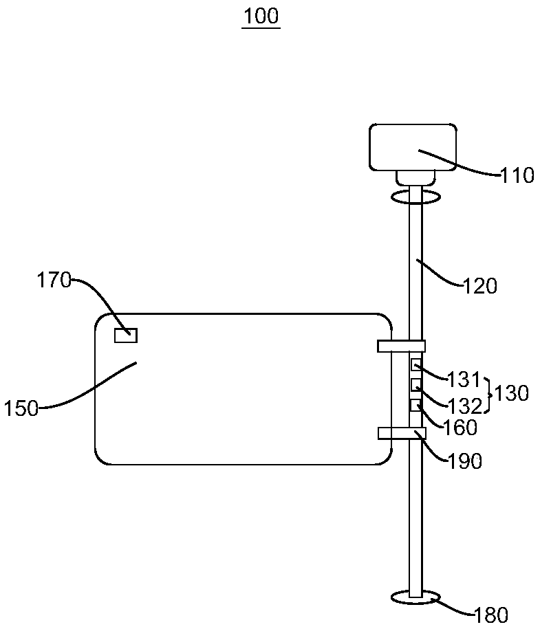
[0043] See figure 1 The embodiment of the invention provides a vehicle indicating device 100, wherein the vehicle indicating device 100 includes a controller 140, a motor 110, a rotating shaft 120, and a display board 150. The display board 150 is connected to the rotating shaft 120, and the motor 110 is connected to the rotating shaft 120. The motor 110 is used to drive the rotating shaft 120 to rotate after starting, so as to drive the position of the display board 150 to change between the inside of the vehicle and the outside of the vehicle.

[0044] Specifically, in this embodiment, the motor 110 is a stepping motor 110. The stepping motor 110 converts an electrical pulse excitation signal into a corresponding discrete value of angular displacement or linear displacement to control the motor. Pulse moves one step, so it is also called pulse motor. That is, the motor provided in this embodiment can be controlled by the chip to move. In addition, the rotor shaft of the motor ...

no. 2 example

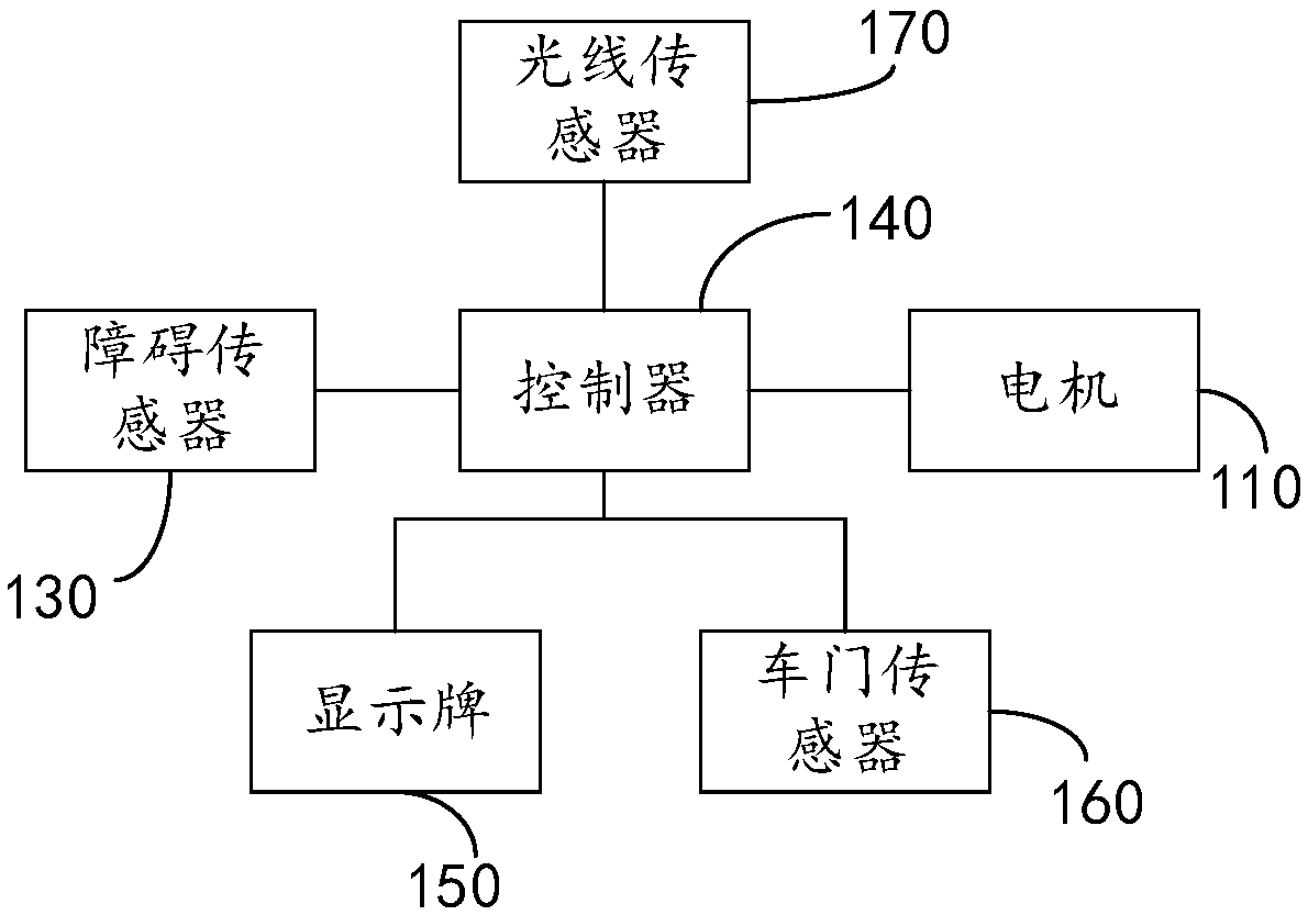
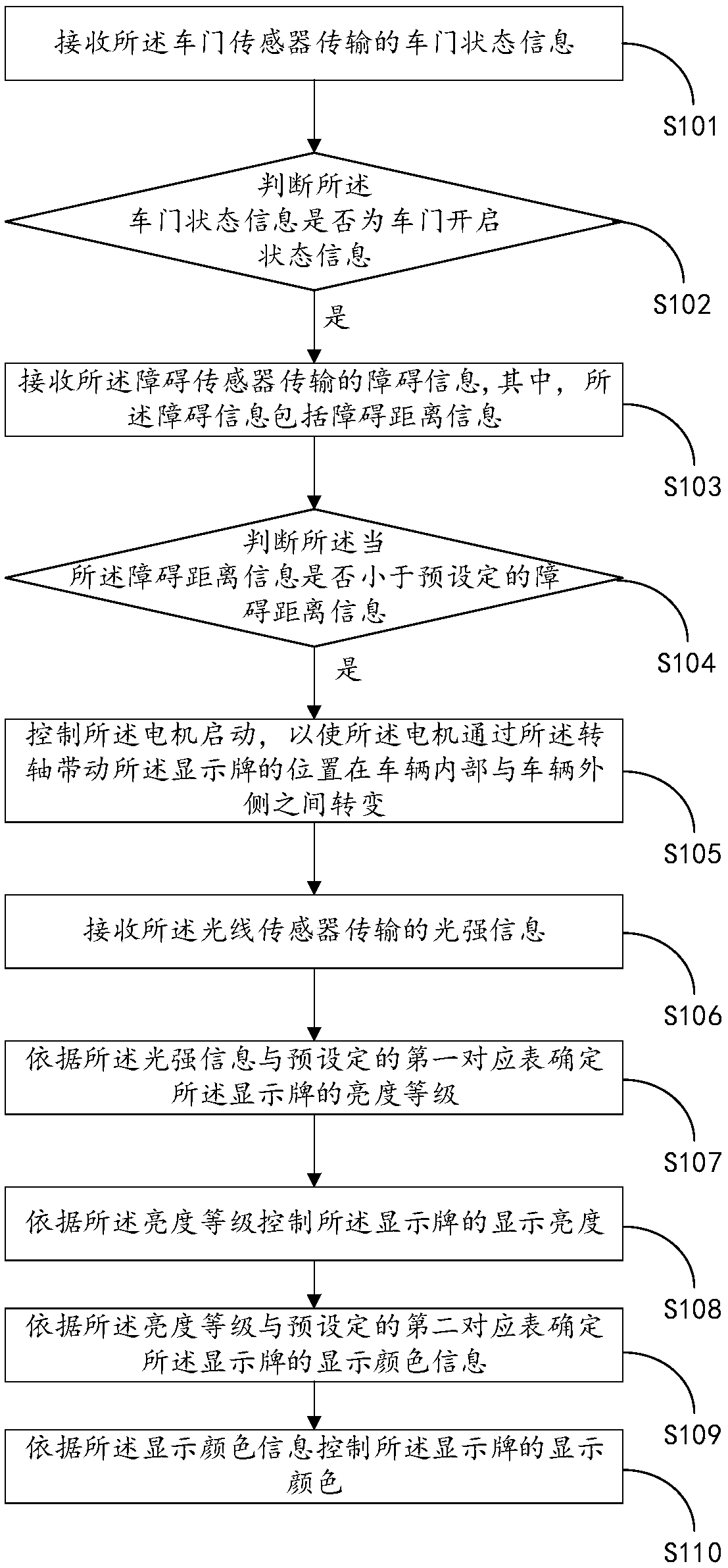
[0078] See figure 2 The embodiment of the present invention provides a method for controlling a vehicle indicating device 100, which is applied to the controller 140. The vehicle indicating device 100 further includes a motor 110, a rotating shaft 120, an obstacle sensor 130, a display board 150, a light sensor 170, and a door sensor 160 The controller 140 is electrically connected to the motor 110, the obstacle sensor 130, the display card 150, and the light sensor 170, respectively. The display card 150 is connected to the rotating shaft 120, and the motor 110 is connected to the rotating shaft 120. The control method of the vehicle indicating device 100 includes:

[0079] Step S101: Receive door state information transmitted by the door sensor 160.

[0080] In this embodiment, the door status information includes an open state or a closed state. The door sensor 160 provided in this embodiment is installed on the shaft 120, and the shaft 120 is installed at the door. The door sen...


PUM


Abstract

The invention provides a vehicle indicating device and a method for controlling the vehicle indicating device, which relates to the technical field of vehicle signal indicating. The vehicle indicatingdevice comprises an electric motor, a rotating shaft and a display board, wherein the display board is connected with the rotating shaft, and the electric motor is connected with the rotating shaft;and the electric motor is used for driving the rotating shaft to rotate after starting so as to drive the position of the display board to change between the interior and the exterior of the vehicle.The vehicle indicating device and the method for controlling the vehicle indicating device have the advantages of making passengers more convenient.

Description

Technical field [0001] The present invention relates to the technical field of vehicle signal indication, and in particular to a vehicle indication device and a control method of the vehicle indication device. Background technique [0002] Cars are the most common means of transportation that we encounter in daily life. For example, various public transportation (buses, buses) and other urban transportation are extremely common in various cities. It plays a very important role in urban transportation. Role, the indication information of public transportation now has the mobile phone APP terminal, the public number, the display board of the bus stop, and the indication of the public transportation itself. With the development of technology, the indication information of the public transportation is becoming more and more perfect, but In a bus station with a very large passenger flow and traffic flow, there are often multiple buses lined up close to the end. In this case, any traff...

Claims


Application Information

Patent Timeline
IPC IPC(8): B60R13/10
CPCB60R13/10
Inventor 张亚红鲁国强赵前进
Owner YINLONG ENERGY CO LTD
Why Eureka
Try Eureka