Vehicle-mounted three-dimensional self-generating seat

A self-generating and seat technology, which is applied in chairs, current collectors, electric vehicles, etc., can solve the problems of small energy utilization, low power generation efficiency, and low use value, and achieve energy saving, power generation efficiency, and passenger convenience. Effect

Inactive Publication Date: 2015-06-17
SHANGHAI JIAOTONG UNIV
View PDF6 Cites 0 Cited by
  • Summary
  • Abstract
  • Description
  • Claims
  • Application Information

AI Technical Summary

Problems solved by technology

[0003] Most of the existing energy conversion devices generate power in the form of simple coils and magnets moving relative to each other. The power generation efficiency is low, the voltage is small, and the current and output are unstable. For example, the patent 201020570877 "A Generating Seat", although it propose A structure that converts vibrating mechanical energy into electrical energy, but the structure is too simple. Only one gear drives the motor to generate electricity, and it can generate electricity every time you sit down. The energy that can be used is small, so its power generation efficiency is low and its application value is not high; Patent CN201110259920.1 "Power Generation Seat" adopts a structure that vibrates up and down to drive the coil to move and generate power. It uses the electric energy when sitting down for a single time, and the energy density is low; the length of the spring is too long, and the overall power generation device is too large , installation and aesthetics are not ideal, coil power generation is used, and the power generation efficiency is not high; patent CN201220371957.3 "Photovoltaic Power Generation Seat" uses solar panels to generate electricity, and its cost is high; solar power panels are easily damaged and not firm; and large Most seats are installed indoors without direct sunlight, so it is difficult to promote and the use value is not high

Method used


Image

  • Vehicle-mounted three-dimensional self-generating seat
  • Vehicle-mounted three-dimensional self-generating seat
  • Vehicle-mounted three-dimensional self-generating seat

Examples


Embodiment Construction

[0036] A specific embodiment of a vehicle-mounted three-dimensional self-generating seat of the present invention will be described below with reference to the accompanying drawings.

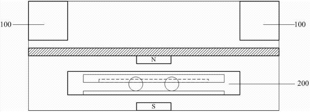
[0037] A vehicle-mounted three-dimensional self-generating seat of the present invention includes: a vibration generating device 100 and a shaking generating device 200 . The vibration power generation device 100 and the shaking power generation device 200 are installed in the seat cushion of the vehicle-mounted three-dimensional self-generating seat; the seat cushion is divided into two layers, the vibration power generation device 100 is installed on the upper layer, and the shaking power generation device 200 is installed on the lower layer, and the two layers are separated by a partition board , specifically as figure 1 shown.

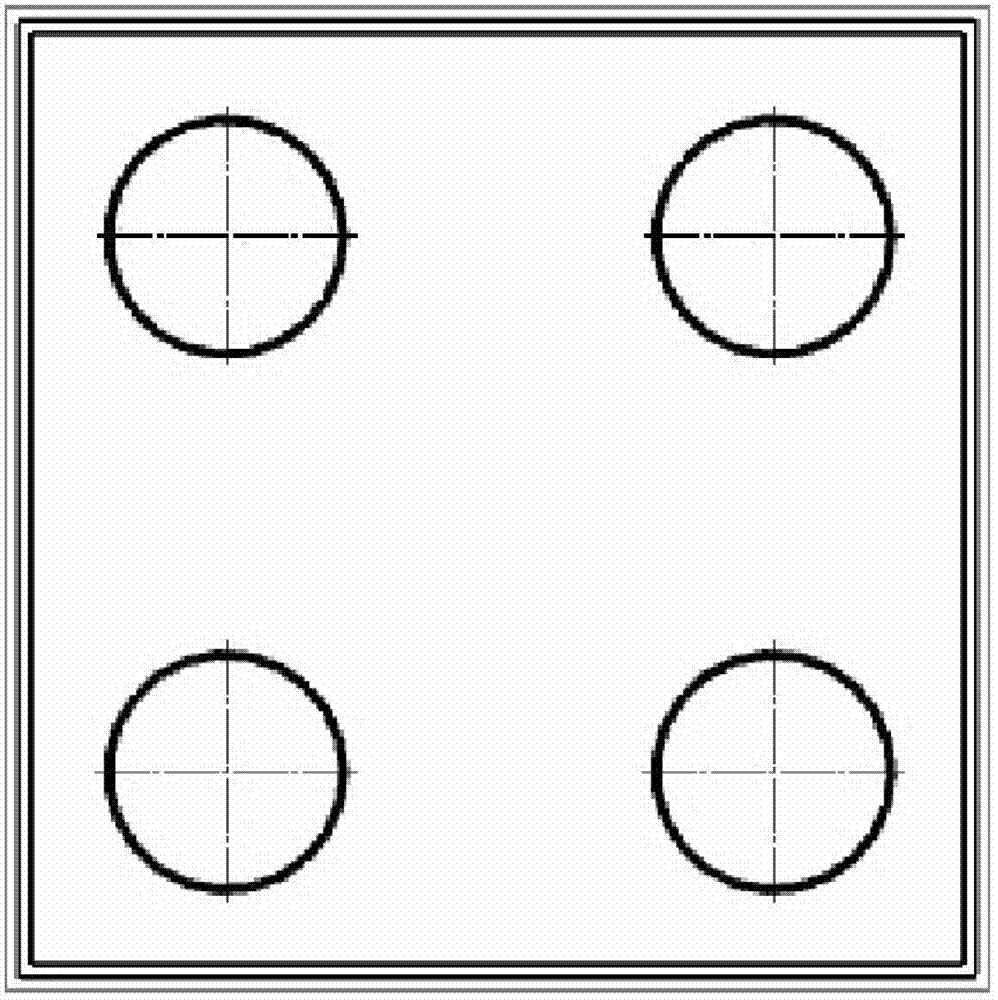
[0038] There are generally 4 groups of vibration power generating devices 100, which are respectively located at the four corners of the seat cushion. Such as fi...


PUM


Abstract

The invention discloses a vehicle-mounted three-dimensional self-generating seat which comprises vibration power generating devices and a rocking power generating device, which are positioned in a seat cushion respectively. Each vibration power generating device comprises a housing and a vibration power generating structure. The housing of each vibration power generating device comprises an upper sleeve, a lower sleeve, an upper baffle and a lower baffle, and each vibration power generating structure comprises a spring, a rack, a metal plate, an acceleration gear, a left side ratchet wheel, a right side ratchet wheel, a right side power generator, a right side power generator, a left side flywheel and a right side flywheel. The rocking power generating device comprises a housing, a power generating coil plate, balls and permanent magnets, wherein the power generating coil plate is connected with a bottom plate of the housing through the balls. When a vehicle body vibrates, the racks drive the acceleration gears to rotate, and then drive the ratchet wheels to rotate, thereby driving the power generators to generate power. When the vehicle body rocks, vertical magnetic induction lines are cut by a coil to generate current. In addition, the current generated by the vibration power generating devices and the rocking power generating device is connected into a rectification circuit and a charging circuit through wires and charged into a storage battery at last so as to facilitate power supply of an external application circuit.

Description

technical field [0001] The invention relates to a self-generating seat, in particular to a vehicle-mounted three-dimensional self-generating seat. Background technique [0002] All kinds of traffic equipment will produce bumps and vibrations and rock back and forth during driving, resulting in energy loss, and at the same time, it will also cause shocks to passengers and cause discomfort. If this part of vibration energy is collected, transformed and utilized, a lot of energy can be saved and the comfort of passengers can be improved. If these electric energies can be rationally utilized at the same time, it will greatly facilitate passengers and greatly improve the ride experience. [0003] Most of the existing energy conversion devices generate power in the form of simple coils and magnets moving relative to each other. The power generation efficiency is low, the voltage is small, and the current and output are unstable. For example, the patent 201020570877 "A Generating S...

Claims


Application Information

Patent Timeline
Patent Type & Authority Patents(China)
IPC IPC(8): A47C7/62A47C1/00H02J7/32
Inventor 姚晔苏康宁卢思宇
Owner SHANGHAI JIAOTONG UNIV
Why Eureka
Try Eureka