Reformer, reforming unit, and fuel cell system

a fuel cell and reforming unit technology, applied in the direction of electrochemical generators, sustainable manufacturing/processing, chemical/physical/physicochemical processes, etc., can solve the problems of increasing the load applied to the reforming catalyst, the limited volume of the reforming catalyst can be filled, and the insufficient reforming treatment, etc., to achieve efficient and stable power generation, facilitate the application to a household use, and facilitate the effect of expansion

Inactive Publication Date: 2010-02-18
IDEMITSU KOSAN CO LTD +1
View PDF3 Cites 15 Cited by
  • Summary
  • Abstract
  • Description
  • Claims
  • Application Information

AI Technical Summary

Benefits of technology

[0116]Accordingly, a small system configuration capable of efficient and stable power generation can be pro

Problems solved by technology

However, according to such a conventional arrangement as in the patent document 1 or 7, which uses the double-pipe reforming pipe filled with the reforming catalyst, only a limited volume of the reforming catalyst can be filled.
Thus, reforming treatment may not be sufficiently obtained.
In addition, load applied on the reforming catalyst

Method used


Image

  • Reformer, reforming unit, and fuel cell system
  • Reformer, reforming unit, and fuel cell system
  • Reformer, reforming unit, and fuel cell system

Examples


first exemplary embodiment

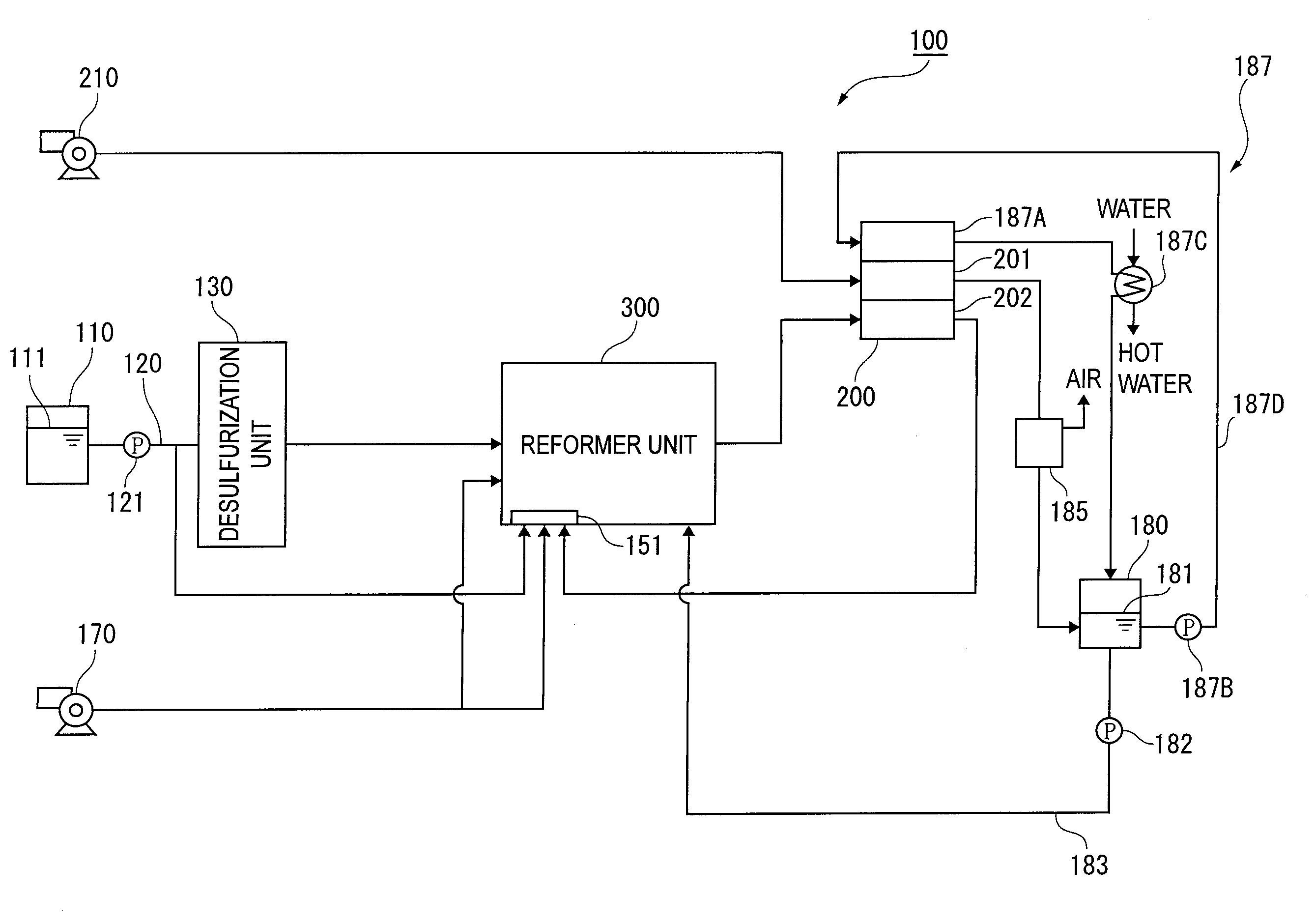
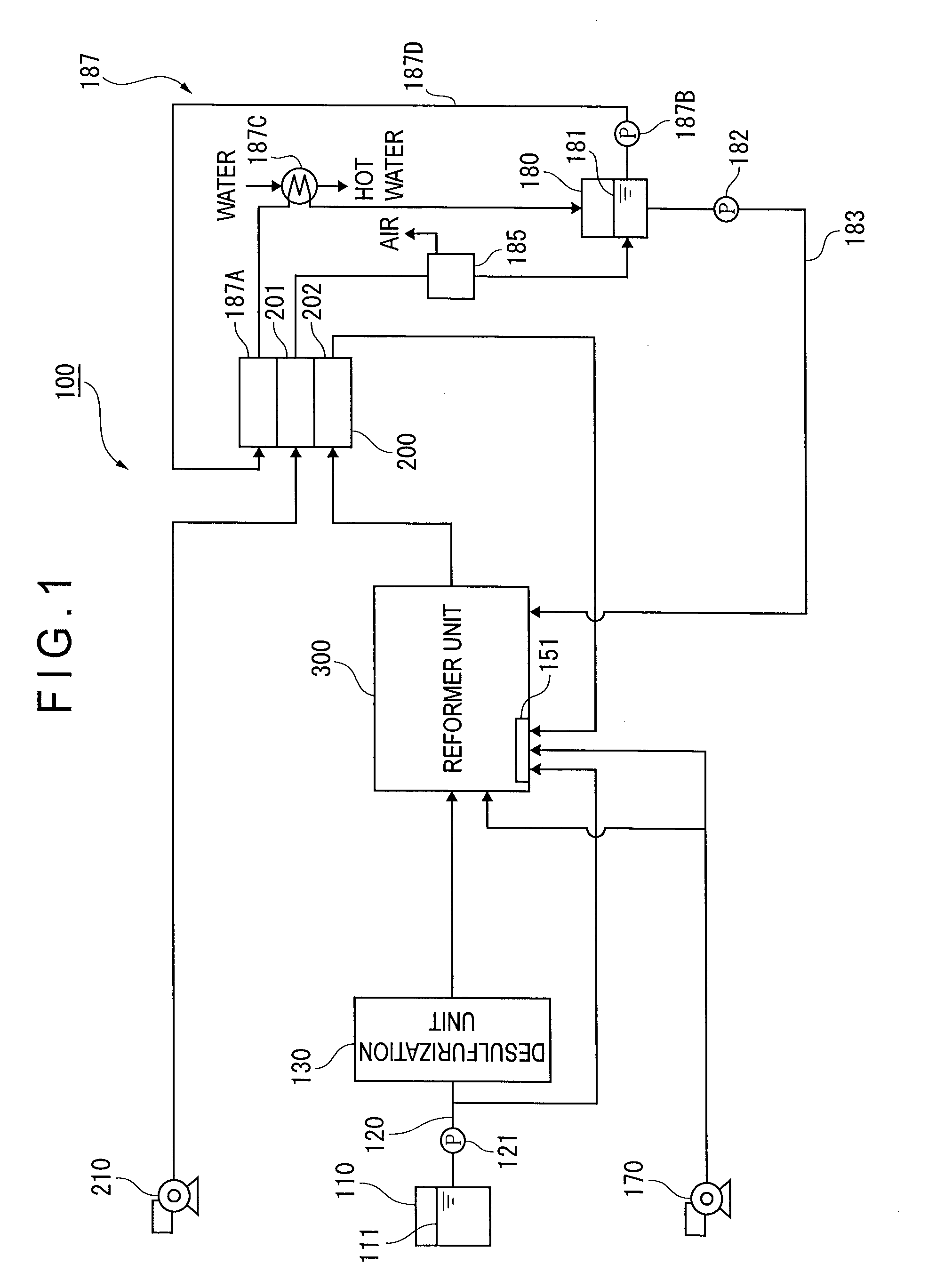
[0154]A first exemplary embodiment of a fuel cell system according to the invention will be described below.

[0155]While the fuel cell system of this first exemplary embodiment exemplarily includes a reformer unit having a reformer according to the invention, the reformer unit or the reformer is not limitedly configured for use in such a fuel cell system but may be configured as, for instance, a hydrogen-gas manufacturing apparatus for single use. Further, while a liquid fuel is exemplarily used as a material gas for mixture with steam, the material gas is not limitedly prepared by use of such a liquid fuel but may be prepared by mixing steam to a hydrocarbon material gas such as liquefied petroleum gas and city gas. In short, various hydrocarbon material gases are also usable. Moreover, while the fuel cell system is exemplarily configured as a household system, the fuel cell system may alternatively be configured as a comparatively large system for use in, for instance, collective h...

second exemplary embodiment

[0253]A second exemplary embodiment of a fuel cell system according to the invention will be described below.

[0254]In this second exemplary embodiment, description duplicated in the first exemplary embodiment will be simplified or omitted.

[0255][Arrangement of Fuel Cell System]

[0256](Overall Arrangement)

[0257]The overall arrangement of the fuel cell system according to this second exemplary embodiment is the same as the first exemplary embodiment, description of which is omitted.

[0258](Reformer Unit)

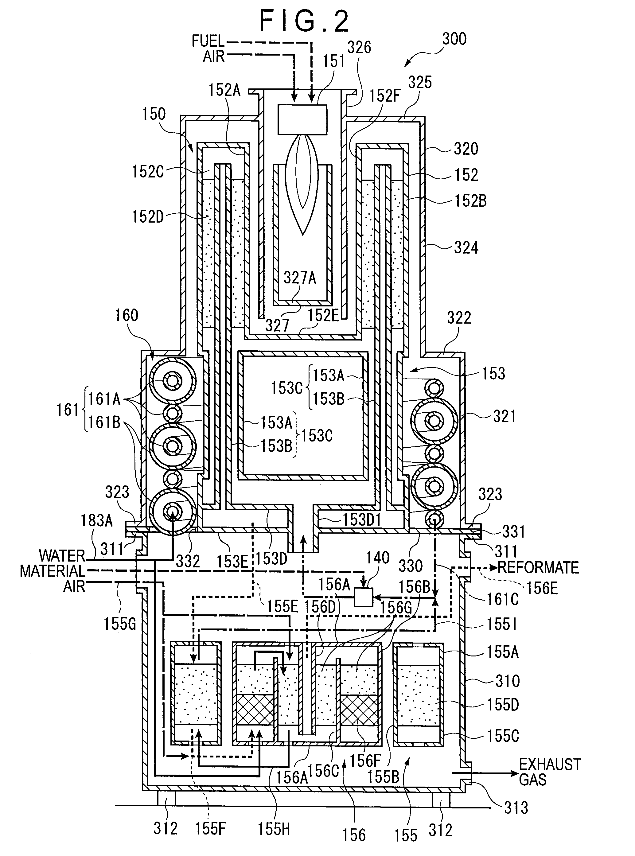
[0259]Next, an arrangement of the reformer unit 300 of the above-described fuel cell system 100 according to the second exemplary embodiment will be described.

[0260]FIG. 2 is a conceptual diagram schematically showing an arrangement the reformer unit.

[0261]As in the first exemplary embodiment, the reformer unit 300 according to the second exemplary embodiment is configured as a unit that includes the carburetor 140, the reformer 150, the CO transform unit 155, the CO selective-oxidation ...

third exemplary embodiment

[0295]A third exemplary embodiment of a fuel cell system according to the invention will be described below.

[0296]In this third exemplary embodiment, the circulation portion 153 in the first exemplary embodiment is arranged differently. The other arrangements remain the same, so that description thereof will be simplified or omitted.

[0297]FIG. 5 is a conceptual diagram schematically showing an arrangement of a reformer unit according to the third exemplary embodiment.

[0298]In FIG. 5, the reformer container 152 of the reformer 150, which includes the inner cylindrical body 152A and the outer cylindrical body 152B having different diameters but the substantially coincident center axes, is shaped in a substantially annular cylinder in which the reforming chamber 152C of a substantially annular space is defined between the inner cylindrical body 152A and the outer cylindrical body 152B. As in the first exemplary embodiment, the reformer container 152 is not limitedly structured to inclu...


PUM


Abstract

A reformer includes: a reformer container in which a reforming chamber having a substantially annular space filled with a reforming catalyst is defined; a heater disposed substantially on a center axis of the reformer container; and a circular portion having a plurality of double-pipe structures each of which includes: a feed pipe connected to a first axial end of the reformer container for feeding the material gas to a first axial end of the reforming chamber; and a return pipe substantially coaxially fitted into the feed pipe such that its first end penetrates the reforming chamber and opens in a vicinity of a second axial end within the reforming chamber so as to allow the reformate generated by reforming the material gas to flow thereunto. The reformer provides an efficient and stable reforming treatment with a simplified structure.

Description

TECHNICAL FIELD [0001]The present invention relates to a reformer for conducting a reforming treatment with use of reformer agent filled therein, a reformer for generating reformate containing hydrogen gas by heating a material containing a hydrocarbon material with combustion gas of a burner, a reformer unit, and a fuel cell system including the reformer or the reformer unit.BACKGROUND ART [0002]To date, exemplarily for fuel cell systems, various reformers for reforming fed material gas with reformer agents and generating hydrogen gas have been known. Such a reformer has a double-pipe structure having void portions in a radially multi-ringed manner, and heats material gas mixed with steam with combustion by a burner (heater) substantially centrally disposed for reforming the material gas (e.g., a patent document 1 or 7).[0003]For another fuel cell system, various reformers for reforming fed material gas with reformer agents while heating the material gas with burners and generating...

Claims


Application Information

Patent Timeline
IPC IPC(8): B01J19/00
CPCB01J8/0257Y02E60/50B01J8/0285B01J8/0484B01J2208/00203B01J2208/00309B01J2208/00504B01J2208/0053B01J2208/00849B01J2208/025C01B3/384C01B2203/0233C01B2203/0816C01B2203/0822C01B2203/0827C01B2203/0872C01B2203/12H01M8/0618H01M8/0631B01J8/0278Y02P20/10C01B3/38H01M8/06
Inventor HIGASHINO, KAZUYUKIKOMAZAWA, AKIHIKOWATANABE, MISAOTOKITA, YOSHIJI
Owner IDEMITSU KOSAN CO LTD
Why Eureka
Try Eureka