Wind power generation system

a power generation system and wind turbine technology, applied in the direction of wind motors, wind motor combinations, motors, etc., can solve problems such as loss of devices, and achieve the effect of facilitating maintaining an air quantity

Active Publication Date: 2018-03-27
HITACHI LTD
View PDF29 Cites 3 Cited by
  • Summary
  • Abstract
  • Description
  • Claims
  • Application Information

AI Technical Summary

Benefits of technology

[0006]For the arrangements described in JP 2012-233481 A and JP 2012-072684 A, which use natural wind to allow heat inside the wind power generation systems to dissipate into the ambient air as described above, it is important to introduce a large quantity of air to the radiator or the devices to be cooled in order to cool the devices efficiently. Additionally, wind power generation systems demand mitigation of wind load and reduction in size and weight of a nacelle for improved reliability and reduced costs. Furthermore, for efficient and stable power generation, it is desirable to curb waste and disturbance, caused by the location and configuration of a nacelle and a radiator, of wind to be applied to blades. It is therefore an object of the present invention to provide a wind power generation system including a path arrangement that facilitates maintaining an air quantity for cooling by natural wind to achieve effective cooling in a nacelle.
[0009]This invention allows a wind power generation system to be provided, which includes a path arrangement that facilitates maintaining an air quantity for cooling by natural wind in order to achieve effective cooling in a nacelle.

Problems solved by technology

Devices housed in the wind power generation system, such as the generator, the gearbox, the power converter, and the transformer, generate heat, which is the loss from the devices.

Method used


Image

  • Wind power generation system
  • Wind power generation system
  • Wind power generation system

Examples


first embodiment

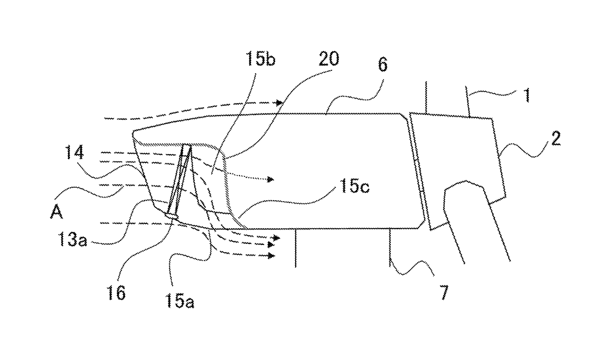
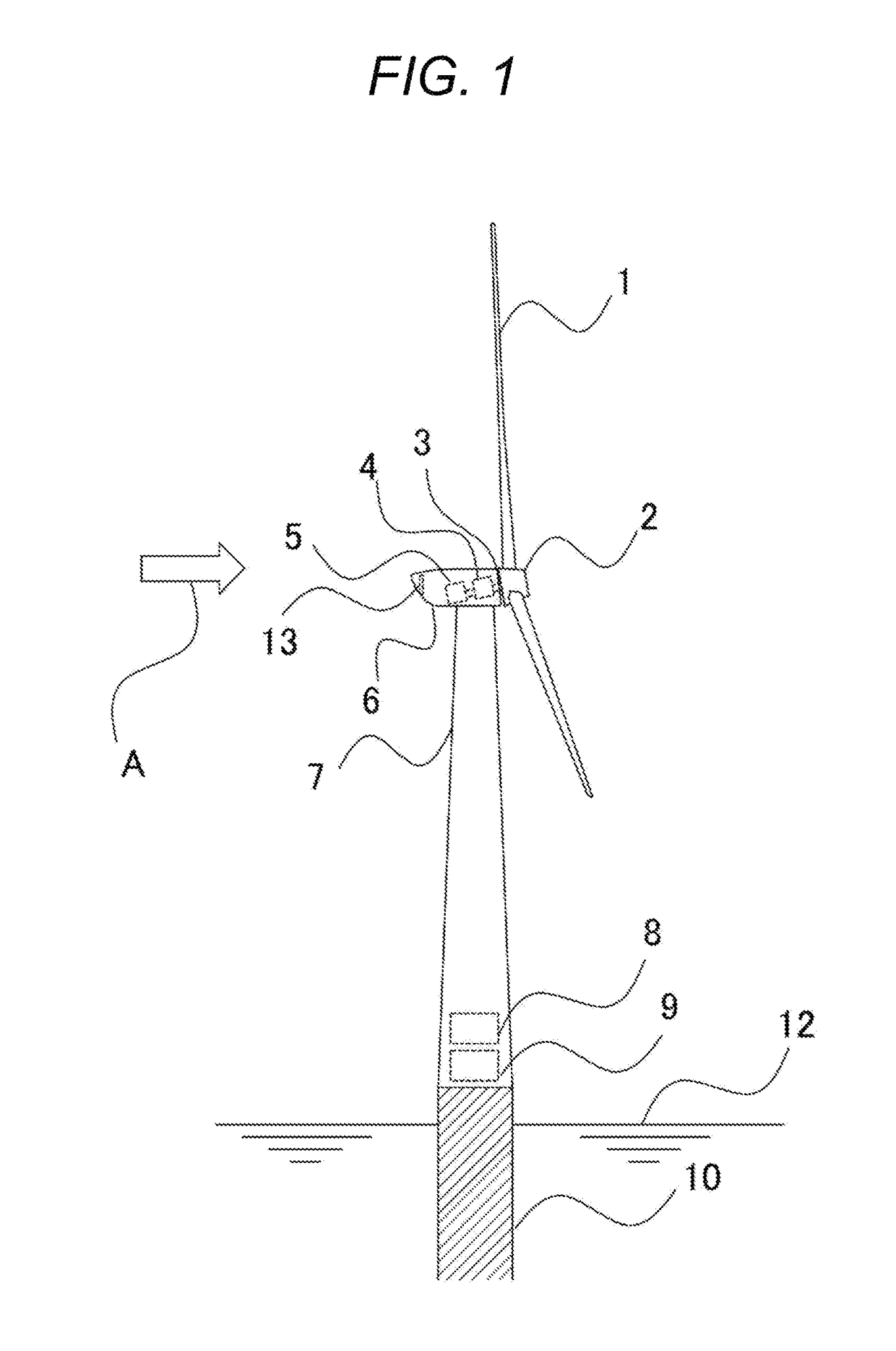
[0018]A first embodiment will now be described with reference to FIGS. 1 and 2.

[0019]FIG. 1 is a schematic view of a wind power generation system for offshore installation according to the first embodiment. The wind power generation system includes a tower 7, which is installed offshore to protrude from underwater, and a nacelle 6, which is located at the top of the tower 7. The nacelle 6 supports pivotally a rotor 2 provided with blades 1 and a hub (not shown). The rotor 2 is connected through a main shaft 3 and a gearbox 4 to a generator 5. The generator 5 is connected through a power cable (not shown) to electrical items, such as a power converter 8 and a transformer 9, housed in a lower portion of the tower 7. The wind power generation system uses a coolant, which contains antifreeze, as a cooling medium to cool the generator 5 and the gearbox 4. The wind power generation system includes a radiator 13 into which the coolant is introduced. The radiator 13 is supported on an exter...

second embodiment

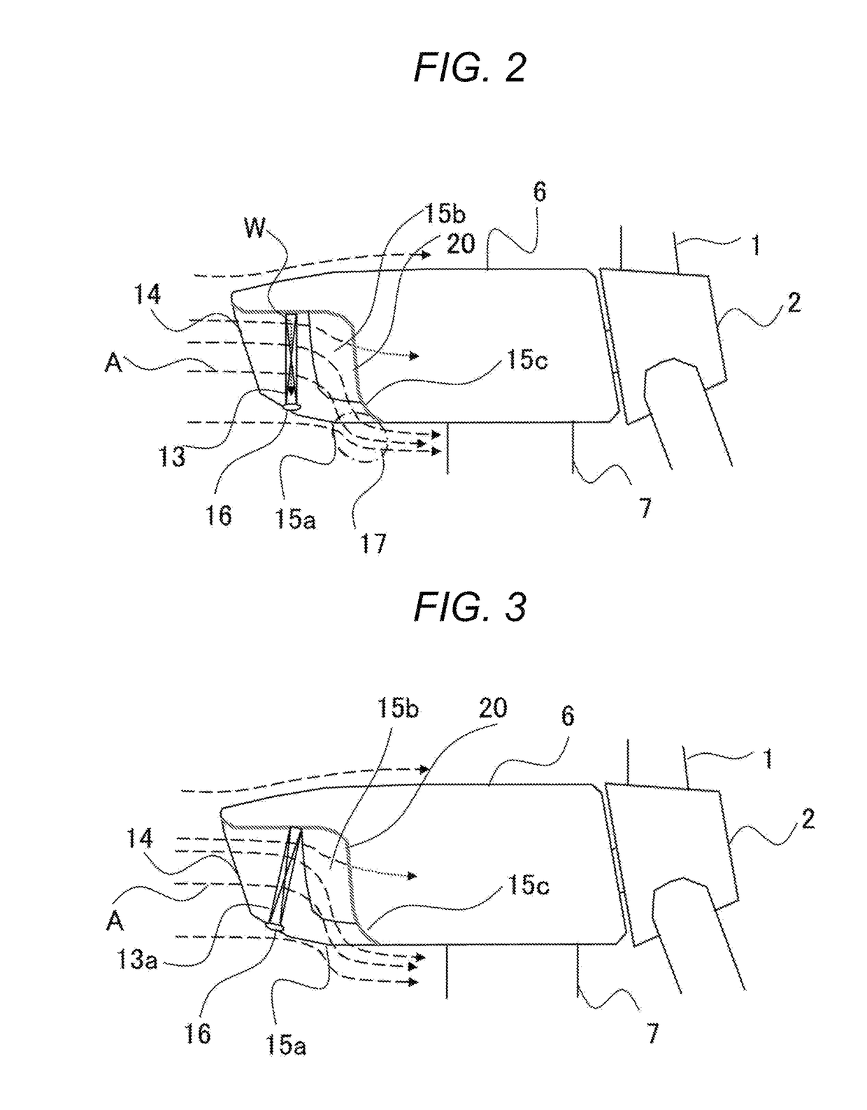
[0041]A second embodiment of the invention will now be described with reference to FIG. 3. Similar descriptions to the first embodiment will be omitted. FIG. 3 is a schematic side view of a nacelle 6 of a wind power generation system according to this embodiment. Note that FIG. 3 includes a sectional side view of a radiator 13a and its surroundings to describe an arrangement of the radiator 13a. The radiator 13a is inclined with its intake surface facing upward.

[0042]While an upright position of the radiator to face upwind is desirable to receive natural wind effectively, a maximized size of the radiator is suitable to ensure cooling capability. In this embodiment, a primary air outlet 15a is provided in the bottom of the nacelle 6. Thus, by inclining the radiator 13a in a manner such that the direction perpendicular to the intake surface of the radiator 13a is slightly raised from the horizontal direction at the upwind side, fins of the radiator 13a, thus tilted downward, acts as g...

third embodiment

[0043]A third embodiment of the invention will now be described with reference to FIG. 4. Similar descriptions to the embodiments described above will be omitted. FIG. 4 is a schematic horizontal plan view observed from downward of a nacelle 6 of a wind power generation system according to this embodiment. FIG. 4 includes a horizontal section of a radiator 13b and its surroundings to describe an arrangement of the radiator 13b.

[0044]In this embodiment, primary air outlets 15b are located in both flanks of the nacelle 6. In the second embodiment described above, the radiator 13a is inclined with its intake surface facing upward. In this embodiment, two radiators are arranged next to each other in the flank direction of the nacelle, with adjoining portions of the two radiators inclined toward blades of the nacelle, in other words, toward the downstream side. In other words, the radiators 13b are inclined so that the adjoining portions of the two radiators 13b are located further down...


PUM


Abstract

A wind power generation system includes: blades configured to be rotated by wind; a generator configured to be driven by the rotation of the blades to generate power; a nacelle supporting the blades; and a tower supporting the nacelle rotatably. The wind power generation system is configured to receive the wind at a side opposite to a side of the nacelle on which the blades are provided. The system includes a radiator configured to dissipate heat in the nacelle through a cooling medium. The radiator is provided outside the nacelle on an upwind side of the nacelle. The radiator is provided with an intake surface thereof facing an upwind direction. A path is formed downstream of the radiator to guide the wind that has passed the radiator.

Description

BACKGROUND OF THE INVENTION[0001]1. Field of the Invention[0002]The present invention relates to a wind power generation system that uses natural wind to cool an internal device.[0003]2. Description of the Related Art[0004]In a typical wind power generation system, a rotor, which is rotated by blades, is supported through a main shaft by a nacelle located at the top of a tower. The nacelle often houses a generator, which is rotated by the rotation of the main shaft of the blades. To obtain a suitable rotational speed of the generator, a gearbox is located between the rotor and the generator to increase the rotational speed of the generator in some cases. Electric energy generated by the generator is converted by a power converter and a transformer to electric power that can be supplied to a utility grid.[0005]Devices housed in the wind power generation system, such as the generator, the gearbox, the power converter, and the transformer, generate heat, which is the loss from the devi...

Claims


Application Information

Patent Timeline
Patent Type & Authority Patents(United States)
IPC IPC(8): F03D9/00F03D9/25F03D1/00F03D80/60
CPCF03D80/60F03D1/00F03D9/25Y02E10/726F05B2240/2213Y02E10/721F05B2240/14F03D1/04F05B2260/201Y02E10/72F03D80/80
Inventor FUNABASHI, SHIGEHISASHIGENAGA, YASUSHIINAMURA, SHINGOODA, MASARU
Owner HITACHI LTD
Why Eureka
Try Eureka