Adjustable bollard and an adjusting method thereof

A bollard, adjustable technology, applied in the direction of shipping equipment, etc., can solve the problems of cable breakage, troublesome adjustment, failure of limit fixing device, etc., and achieve the effect of avoiding stumbling and simple operation

Active Publication Date: 2019-01-01
临沂产业研究院有限公司
View PDF5 Cites 2 Cited by
  • Summary
  • Abstract
  • Description
  • Claims
  • Application Information

AI Technical Summary

Problems solved by technology

[0004] 1. Because the cables tied to the pile body will swing from side to side due to the influence of the weather, in the process of friction with the pile body, not only the cable will be broken, but the cable will also drive the pile body to rotate, so that the adjustment rod and the pile body will rotate relative to each other. Leading to the failure of the limit fixing device, there is a big safety hazard;
[0005] 2. Before work, at least two staff members are required to cooperate. One person pulls up the pile body, and the other person rotates the adjustment lever to limit the position, so the adjustment is troublesome; therefore, it is necessary to improve

Method used


Image

  • Adjustable bollard and an adjusting method thereof
  • Adjustable bollard and an adjusting method thereof
  • Adjustable bollard and an adjusting method thereof

Examples


Embodiment Construction

[0042] The following are specific embodiments of the present invention and in conjunction with the accompanying drawings, the technical solutions of the present invention are further described, but the present invention is not limited to these embodiments.

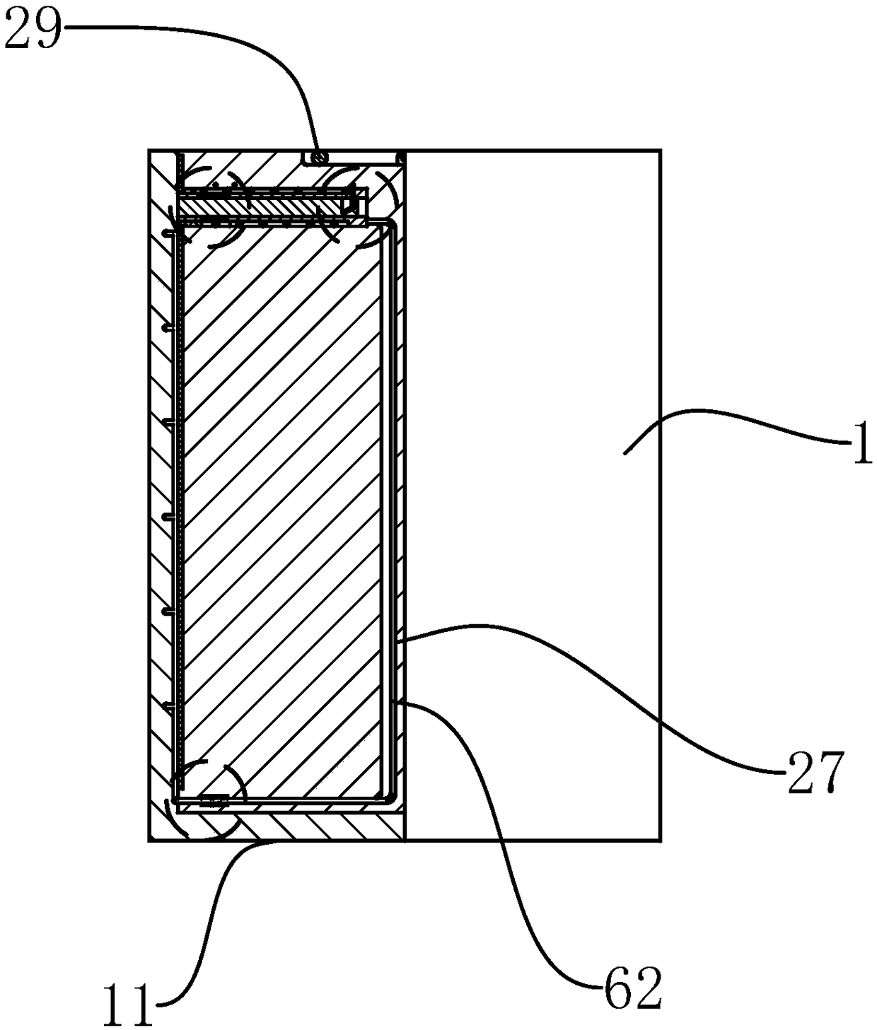
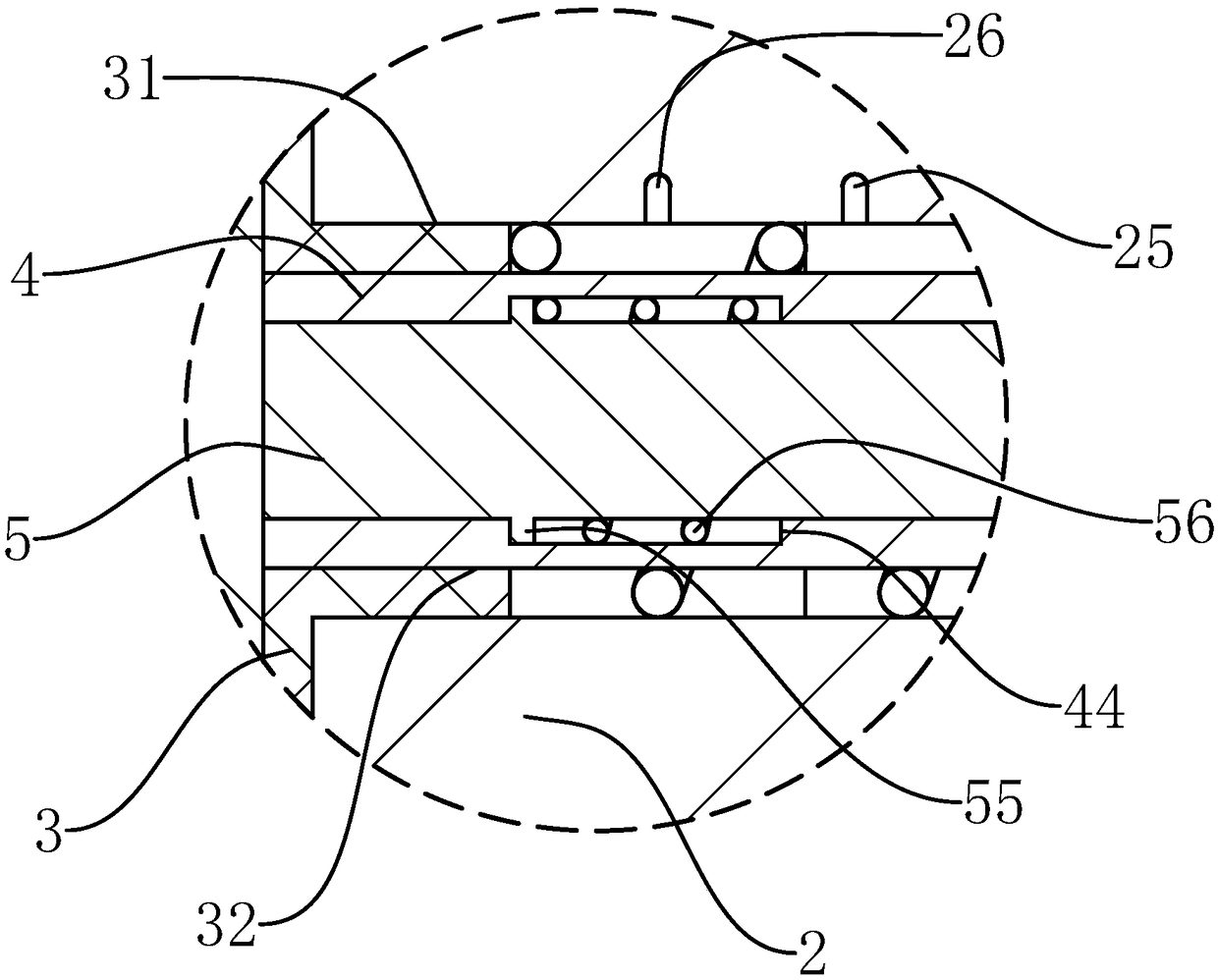
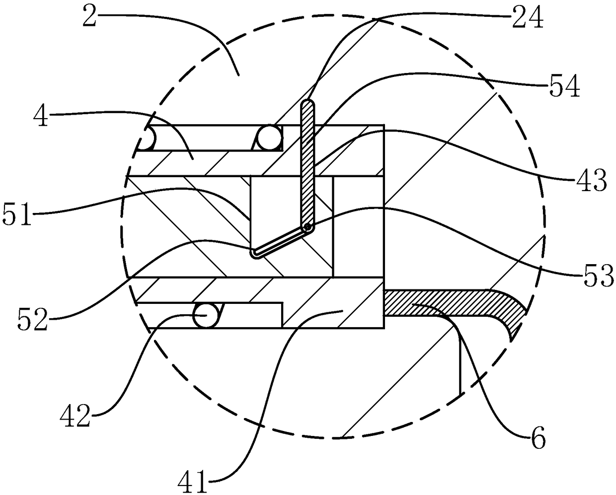
[0043] Such as Figure 1-15 As shown, an adjustable mooring bollard of the present invention includes a cylindrical pile tube 1 embedded below the ground, the top of the pile tube 1 is flush with the ground, and the bottom end of the pile tube 1 is coaxially fixed with a tube plate 11, and also includes Cooperate with the cylindrical pile body 2 embedded in the pile barrel 1, the outer wall of the pile body 2 is coaxially provided with a sleeve-shaped sleeve groove 21, and also includes a circular sleeve-shaped sliding sleeve 3 that fits on the sleeve groove 21, and the outer diameter of the sliding sleeve 3 is The inner diameter of the pile barrel 1 is the same, and the outer wall of the pile body 2 near the top is coaxia...


PUM


Abstract

The invention provides an adjustable bollard and an adjusting method thereof, and belongs to the field of mooring equipment. The problem that an existing bollard is adjusted troublesomely is solved. The adjustable bollard comprises a pile barrel and a pile body, and further comprises a sliding sleeve, a locking mechanism, an adjusting groove, an adjusting tube and an inserting rod, wherein a sleeving groove is formed in the outer wall of the pile body; the sliding sleeve sleeves the sleeving groove; a tube seat is formed in the outer wall of the pile body; the locking mechanism comprises a stopping tube; the front end of the stopping tube is connected with the inner wall of the sliding sleeve; a stopping hole is formed in the inner wall of the stopping tube; the adjusting groove is positioned in the pile body; the adjusting tube penetrates in the stopping hole; the rear end of the adjusting tube penetrates in the adjusting groove; an adjusting rod penetrates in the adjusting tube; a rod groove is formed in the wall of the adjusting rod; a first chute is formed in the bottom of the rod groove; a first slider is arranged on the first chute; an inserting hole is formed in the adjusting tube; the inserting rod penetrates in the inserting hole; the rear end of the inserting rod is fixed to the first slider; an inner slot and an outer slot are formed in the wall of the adjusting groove; and a movable groove is formed in the wall of the tube seat. The bollard has three states, and can be adjusted according to specific application occasions.

Description

technical field [0001] The invention belongs to the technical field of mooring equipment, and relates to an adjustable mooring pile and an adjusting method thereof. Background technique [0002] The bollard is a device installed on the wharf or deck for mooring cables. The existing bollards are generally fixed structures, which protrude when not in use, occupying space, and cause certain safety hazards to passing vehicles and pedestrians; [0003] The existing application number is 201710489072.0, which is a Chinese invention patent application named "a hidden bollard", which discloses a bollard with an adjustable structure. The placement in the barrel can avoid affecting vehicles and pedestrians. When working, pull out the pile body from the placement barrel upwards, fix it with a limit fixing device, and then use the pile body. But it has the following problems: [0004] 1. Because the cables tied to the pile body will swing from side to side due to the influence of the ...

Claims


Application Information

Patent Timeline
Patent Type & Authority Applications(China)
IPC IPC(8): E02B3/24
CPCE02B3/24
Inventor 张丽丽
Owner 临沂产业研究院有限公司
Why Eureka
Try Eureka