Blade device for flow power generation

A blade and fluid technology, which is applied in the field of blade devices for hydropower generation, can solve the problems of not being able to fully function the blades 122 and reducing the power generation efficiency.

Inactive Publication Date: 2019-01-01
黄 国彰
View PDF0 Cites 0 Cited by
  • Summary
  • Abstract
  • Description
  • Claims
  • Application Information

AI Technical Summary

Problems solved by technology

Although this blade device for wind power generation can make full use of the bottom side wind 15 to push the blade 122 to generate electricity, the bottom side wind 15 flows upward after pushing the blade 122 and merges with the positive wind 13. When, a large amount of win

Method used


Image

  • Blade device for flow power generation
  • Blade device for flow power generation
  • Blade device for flow power generation

Examples


Embodiment Construction

[0024] In the following description, similar or identical elements will be denoted by the same reference numerals.

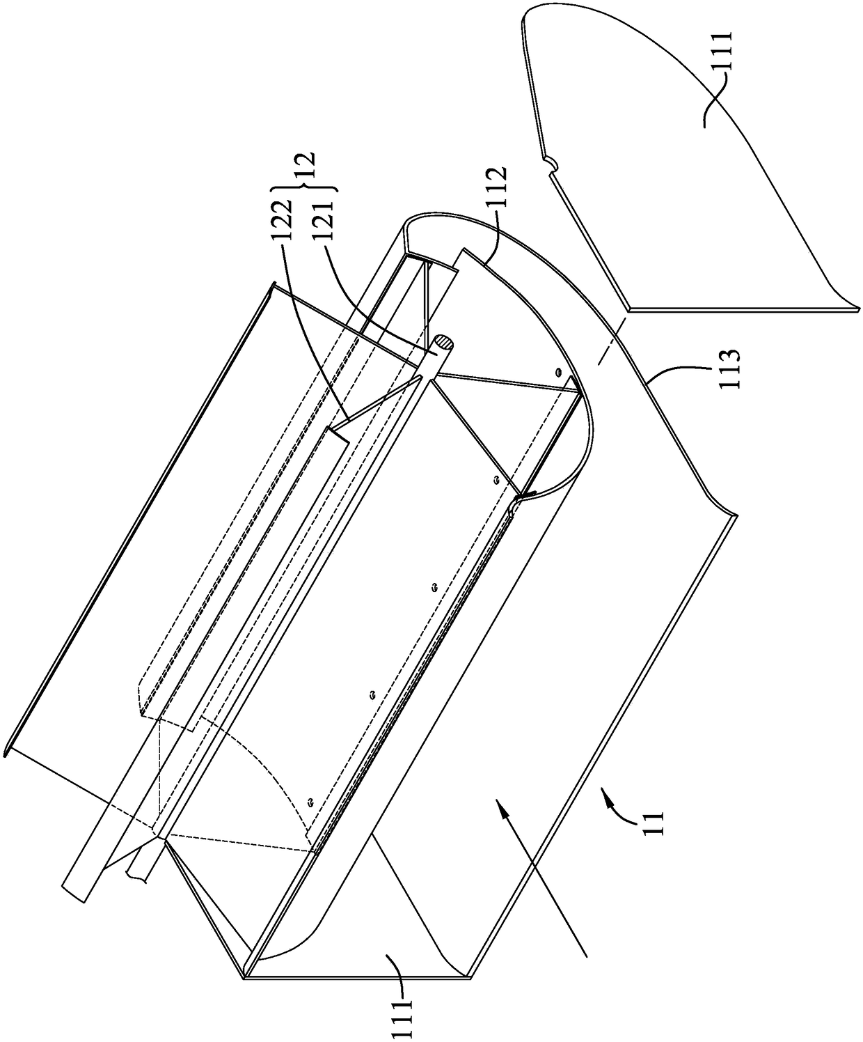
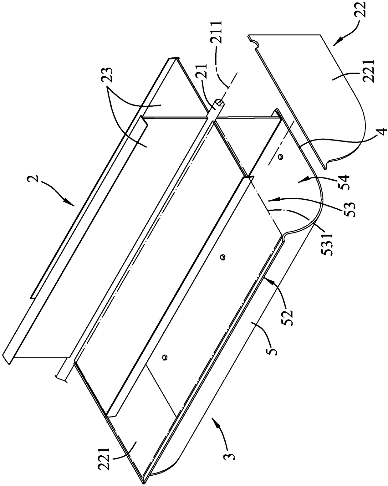
[0025] refer to image 3 and Figure 4 , a first embodiment of the blade device for flow power generation of the present invention is suitable for use with a fluid flowing forward and a generator (not shown). The fluid can be wind or water for wind or hydroelectric power generation. The first embodiment includes a rotating unit 2 and a base unit 3 assembled with the rotating unit 2 .

[0026] The rotating unit 2 includes a rotating shaft 21 extending left and right and connected to the generator set, a first supporting group 22 for pivoting the rotating shaft 21 , and four blades 23 extending radially outward from the rotating shaft 21 . The first supporting group 22 includes two side panels 221 spaced apart from each other and connected to the left and right sides of the base unit 3 respectively. One end of the rotating shaft 21 is rotatably pivoted on a to...


PUM


Abstract

The invention discloses a blade device for flow power generation. The device is suitable for matching a fluid flowing forward to use and includes a rotation unit which can be pushed to rotate by the fluid and drive a generator to generate electricity, and a support unit for the arrangement of the rotation unit. The support unit includes a base plate set arranged under the rotation unit, and a baffle plate which extends upward from the rear side of the base plate set and is in front and rear interval with the rotation unit; the baffle plate includes a bottom end connected to the rear side of the base plate set, and a top end located at the upper rear part of the bottom end; and the fore-and-aft clearance between the top end and the rotation unit is about 1.4 to 3 times the radial length ofthe rotation unit. The device can reduce the influence of the fluid on the bottom side on the fluid in a forward direction, and therefore, the problem that, during previous operation, the fluid in theforward direction is pushed upward by the fluid on the bottom side so that generating efficiency is reduced, can be solved.

Description

technical field [0001] The invention relates to a power generation device of renewable energy, in particular to a blade device for flow power generation. Background technique [0002] refer to figure 1 and figure 2 , a conventional blade device for flow power generation, which is suitable for using fluids such as wind and water to drive a generator (not shown) to generate electricity. In the following description, wind power generation by using forward blowing wind is taken as an example. The blade device for flow power generation includes a base unit 11 and a rotating unit 12 erected on the base unit 11 . The base unit 11 includes two side plates 111 spaced left and right, a baffle plate 112 arranged below the rotating unit 12 and curved to match the actuation track of the rotating unit 12, and a baffle plate 112 located below the baffle plate 112 and The wind collecting plate 113 is curved upward and forward. The rotating unit 12 includes a rotating shaft 121 extendi...

Claims


Application Information

Patent Timeline
IPC IPC(8): F03B3/12F03D1/06
CPCF03B3/121F03D1/0675Y02E10/20Y02E10/72
Inventor 黄国彰
Owner 黄 国彰
Why Eureka
Try Eureka