Solid heat energy storage system with multiloop connectors

A thermal energy storage and multi-circuit technology, applied in heating systems, indirect heat exchangers, heating methods, etc., can solve problems such as insufficient heating capacity of the heating network, limited electricity consumption of thermal power plants, etc., to improve heat release adaptation performance, improve the effect of storage capacity

Pending Publication Date: 2019-01-01
SHENYANG SHIJIE ELECTRIC
View PDF7 Cites 0 Cited by
  • Summary
  • Abstract
  • Description
  • Claims
  • Application Information

AI Technical Summary

Problems solved by technology

However, in the current situation, the growth rate of heat user demand is faster than the growth rate of electricity demand, so that power plants with heat supply users often make way for wind power grid connection, resulting in limited grid power in thermal power plants and insufficient heating capacity of the heat network The phenomenon

Method used


Image

  • Solid heat energy storage system with multiloop connectors
  • Solid heat energy storage system with multiloop connectors

Examples


Embodiment 1

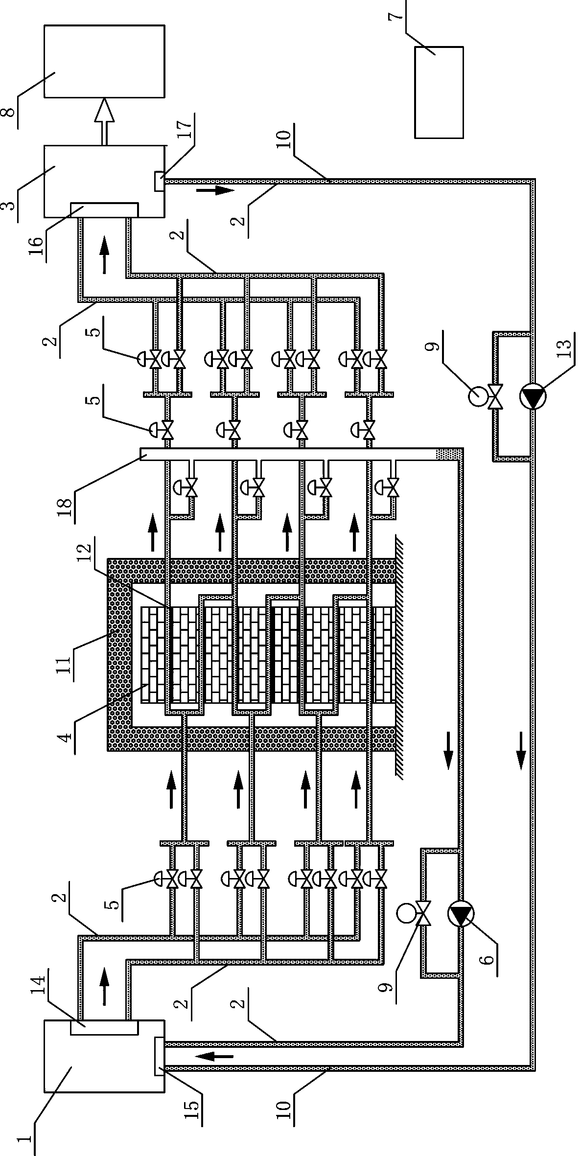
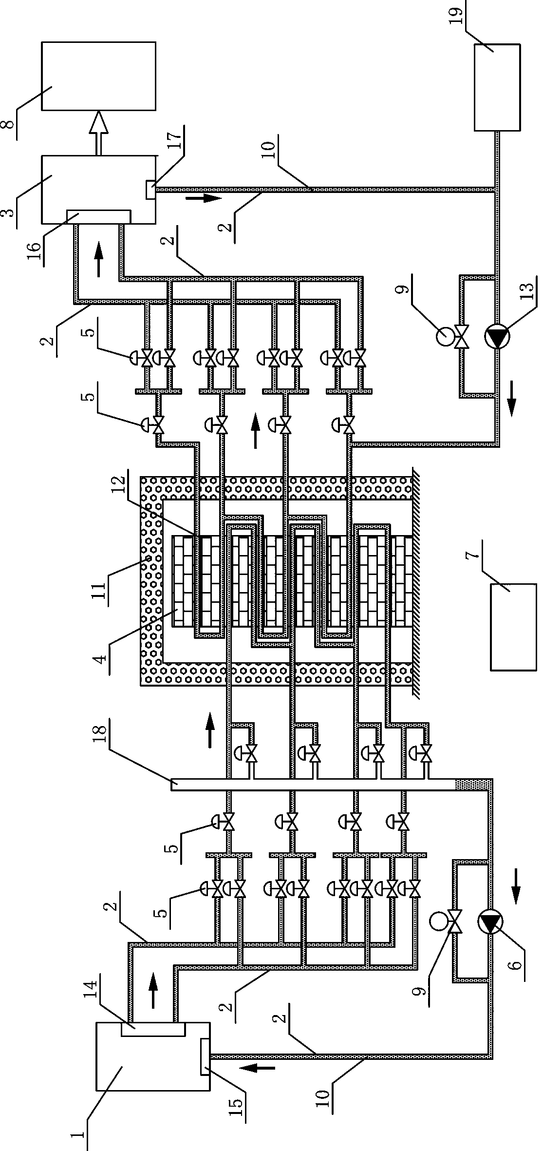
[0021] This example figure 1 As shown, it is a single-structure solid thermal energy storage system with a double-set heat storage loop and a double-set heat release loop interface; figure 2 As shown, it is a multi-group structure solid thermal energy storage system with double-set heat storage loops and double-set heat release loop interfaces. They include: multi-heat source system 1, pipeline 2, multi-heat exchange system 3, solid energy storage body 4, Valve group 5, variable frequency drive, control device 7, heat user 8, bypass valve 9, heat carrier 10, heat preservation layer 11, metal plate 12, heat release variable frequency drive 13, heat release output end 14, heat release return end 15, Heat exchange input end 16, heat exchange return end 17, dredging cavity 18, heat carrier constant pressure supplementary device 19.

[0022] Such as figure 1 The solid energy storage body 4 shown is a high temperature resistant building block body with an insulation layer 11 on t...

Embodiment 2

[0026] Such as figure 2 As shown, in addition to the heat carrier pipes in the solid energy storage body 4, the heat storage and heat release circuits adopt a multi-group structure in which parallel arrays are distributed and installed. figure 1 Heat carrier constant pressure supplementary device 19 is provided in more. The heat carrier constant pressure supplementary device 19, the heat exchange return end 17, and the exothermic frequency conversion drive 13 are connected by a pipeline 2. The purpose is to establish a stable heat release working condition through the heat carrier constant pressure supplementary device 19 arranged at the pump tail of the thermal variable frequency drive 13 . The working process is no longer described in detail.


PUM


Abstract

A solid heat energy storage system with multiloop connectors comprises a multi-heat source system, a pipeline, a multi-heat exchanging system, a solid energy storage body, a valve set, variable frequency drivers, a control device, a heat consumer and a dredging cavity and is technically characterized in that the solid energy storage body is internally provided with heat carrier pipelines which areof a multi-group structure or a single-group structure, and each heat carrier pipeline is arranged in two layers or more; the heat exchanging backflow end of each single-group structure is connectedwith the heat discharging variable frequency driver and then connected with a heat discharging backflow end pipeline, and the heat exchanging backflow end of each multi-group structure is connected with the heat discharging variable frequency driver and then connected with the heat discharging heat carrier pipeline on the bottom layer of the same group; the heat discharging output end is connectedwith the heat carrier pipeline of each layer in the solid energy storage body, the heat discharging backflow end pipelines are connected with the heat storage variable frequency driver and then connected with a pipeline at the bottom end of the dredging cavity, and pipelines at the two ends of the heat storage variable frequency driver are connected with heat storage bypass-valves; and the valveset is arranged on the outer side of a heat preservation layer.

Description

technical field [0001] The invention relates to a solid thermal energy storage system with a multi-circuit interface, which changes the thermal energy storage and thermal energy output of the solid thermal energy storage system by operating the switching state of the variable frequency drive and the valve group arranged at the thermal energy input and output ports control relationship. Background technique [0002] Generally, the heat supply capacity and power generation of thermal power units in coal-fired thermal power plants change synchronously. When the heat supply capacity is improved, the on-grid electricity also increases. However, in the current situation, the growth rate of heat user demand is faster than the growth rate of electricity demand, so that power plants with heat supply users often make way for wind power grid connection, resulting in limited grid power in thermal power plants and insufficient heating capacity of the heat network The phenomenon. The so...

Claims


Application Information

Patent Timeline
Patent Type & Authority Applications(China)
IPC IPC(8): F24D11/00F28D20/00
CPCF24D11/00F28D20/00Y02A30/60Y02E60/14
Inventor 朱建新
Owner SHENYANG SHIJIE ELECTRIC
Why Eureka
Try Eureka