
Diagnosis system and method for electric vehicle battery pack insulation resistance detection circuit

A technology of insulation resistance and detection circuit, which is used in measuring devices, measuring electrical variables, instruments, etc., can solve the problems of difficult development, high cost, and inability to judge the reliability of insulation data in time, so as to ensure the authenticity of insulation values ​​and improve the The effect of pressure rating

Inactive Publication Date: 2019-01-01
CH AUTO TECH CORP CO LTD
View PDF12 Cites 13 Cited by
  • Summary
  • Abstract
  • Description
  • Claims
  • Application Information

AI Technical Summary

Problems solved by technology

The structure of the active detection circuit is complex, the cost is high, and the development is difficult. More and more solutions use the passive method to perform insulation detection.
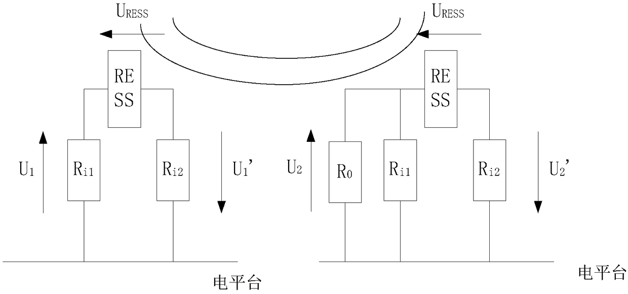
However, when the battery high-voltage system has a large parasitic capacitance to the car body, due to the charging and discharging effect of the capacitance, the passive method detection circuit cannot accurately and effectively measure the insulation resistance value
[0004] The insulation detection method commonly used at present does not have a self-diagnosis function. When the insulation detection circuit itself fails, the fault information cannot be obtained, and the reliability of the insulation data cannot be judged in time.

Method used


Image

  • Diagnosis system and method for electric vehicle battery pack insulation resistance detection circuit
  • Diagnosis system and method for electric vehicle battery pack insulation resistance detection circuit
  • Diagnosis system and method for electric vehicle battery pack insulation resistance detection circuit

Examples


Embodiment Construction

[0034]In order to have a clearer understanding of the technical features, purposes and effects of the invention, the specific implementation manners of the present invention will now be described with reference to the accompanying drawings, in which the same reference numerals represent the same parts.

[0035] For the sake of brevity and intuition in description, the solution of the present invention is described below by describing several representative implementation manners. Numerous details in the embodiments are only used to help the understanding of the solutions of the present invention. But obviously, the technical solutions of the present invention may not be limited to these details when implemented. In order to avoid unnecessarily obscuring the solution of the present invention, some embodiments are not described in detail, but only a framework is given. Hereinafter, "including" means "including but not limited to", and "according to..." means "at least according...


PUM


Abstract

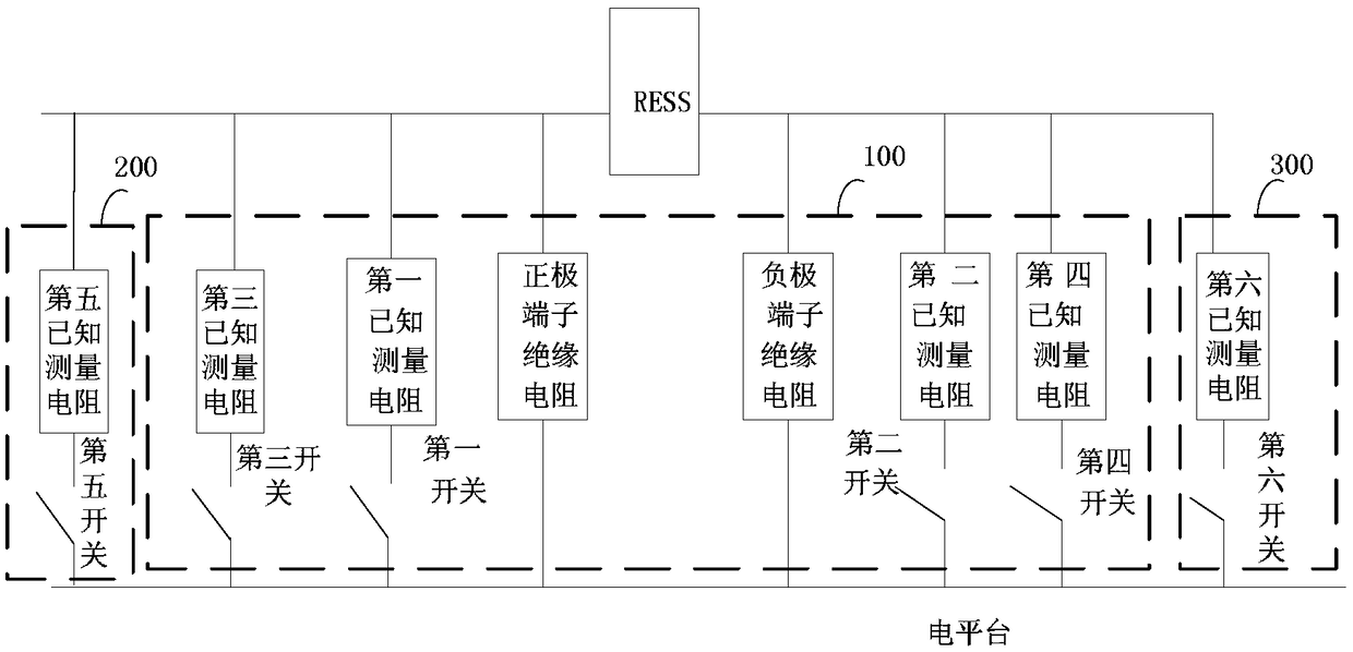
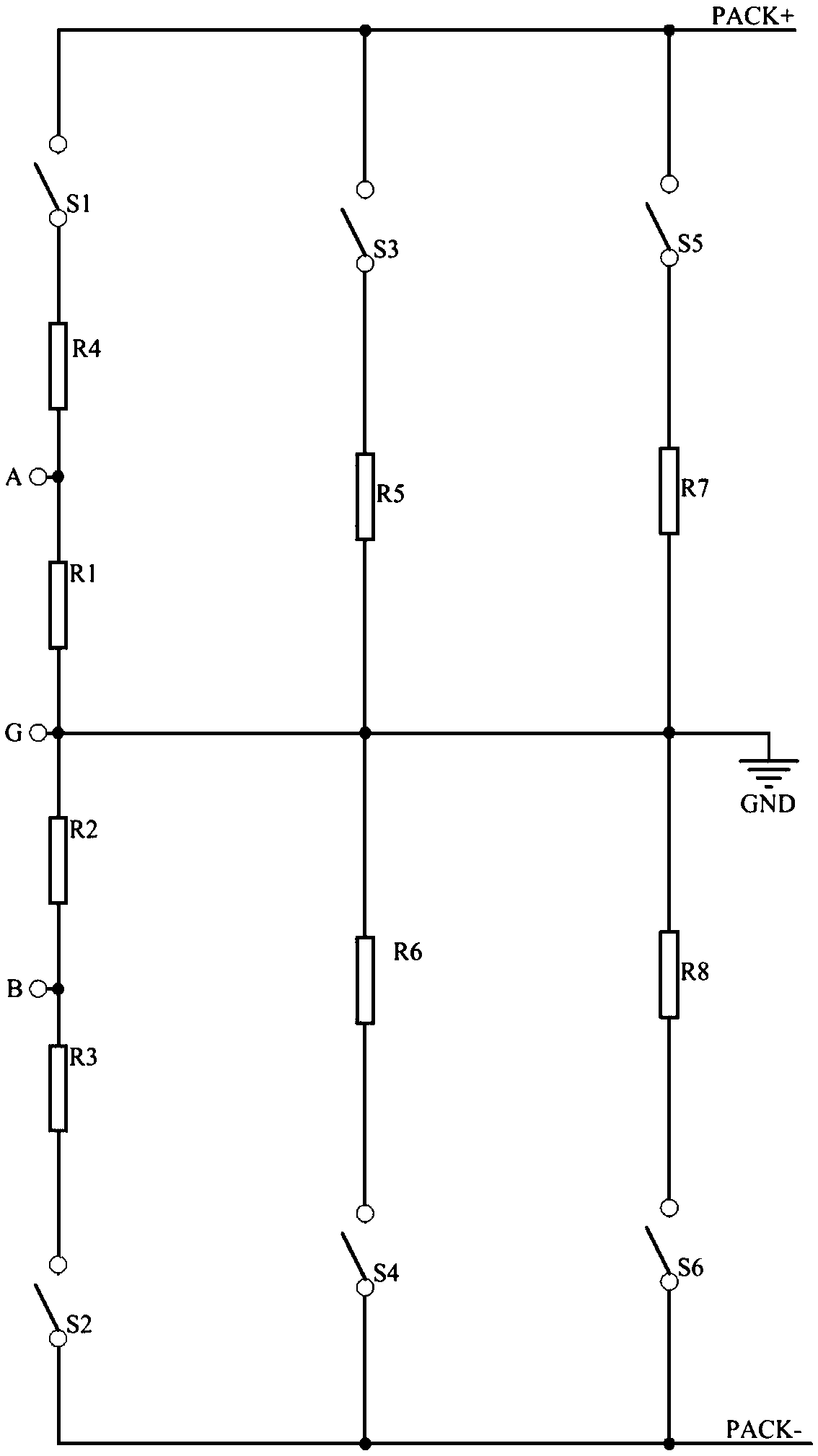
The invention provides a diagnosis system and method for an electric vehicle battery pack insulation resistance detection circuit. According to the diagnosis system and method, a first known measuringresistor and a third known measuring resistor are connected in parallel with the insulation resistor of the positive pole terminal of a battery pack; a second known measuring resistor and a fourth known measuring resistor are connected in parallel with the insulation resistor of the negative pole terminal of the battery pack; a first switch is connected in series with the first known measuring resistor; a second switch is connected in series with the second known measuring resistor; a third switch is connected in series with the third known measuring resistor; a fourth switch is connected inseries with the fourth known measuring resistor; a fifth known measuring resistor is connected in parallel with the insulation resistor of the positive pole terminal of the battery pack; a fifth switch is connected in series with the fifth known measuring resistor; a sixth known measuring resistor is connected in parallel with the insulation resistor of the negative pole terminal of the battery pack; and a sixth switch is connected in series with the sixth known measuring resistor. The diagnosis system and method of the invention can perform diagnosis when the insulation detection circuit fails, and can improve the reliability of insulation data.

Description

technical field [0001] The invention relates to the technical field of automobiles, and more particularly, to a diagnosis system and method for an electric vehicle battery pack insulation resistance detection circuit. Background technique [0002] Energy shortages, oil crises and environmental pollution are intensifying, which have a huge impact on people's lives and are directly related to the sustainable development of the country's economy and society. All countries in the world are actively developing new energy technologies. As a new energy vehicle with reduced oil consumption, low pollution, and low noise, electric vehicles are considered to be an important way to solve the energy crisis and environmental degradation. Hybrid vehicles take into account the advantages of pure electric vehicles and traditional internal combustion engine vehicles at the same time. On the premise of meeting the requirements of vehicle power and mileage, it effectively improves fuel economy...

Claims


Application Information

Patent Timeline
Patent Type & Authority Applications(China)
IPC IPC(8): G01R35/00
CPCG01R35/00
Inventor 陆群张青岭
Owner CH AUTO TECH CORP CO LTD
Learn More