
Mountain area rainfall test method

A technology for rainfall testing and mountainous areas, which is applied in the field of rainfall testing in mountainous areas, can solve the problem that the locator of the rainfall tester is easily damaged, and achieve the effects of reducing the number of times of sun and rain, good rain and sun protection, and easy positioning

Inactive Publication Date: 2019-01-01
李成代
View PDF15 Cites 0 Cited by
  • Summary
  • Abstract
  • Description
  • Claims
  • Application Information

AI Technical Summary

Problems solved by technology

[0004] The purpose of the present invention is to provide a method for measuring rainfall in mountainous areas, which solves the problem that the locator of the rainfall meter is easily damaged due to the long-term exposure to the sun and rain, and the destruction of surrounding animals.

Method used


Image

  • Mountain area rainfall test method
  • Mountain area rainfall test method
  • Mountain area rainfall test method

Examples


Embodiment 1

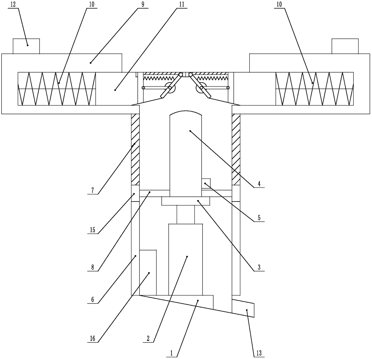
[0037] Such as Figure 1-Figure 4 Shown, a kind of mountain rainfall testing method of the present invention comprises the following steps:

[0038] Step A: Install the tester body 4 below the ground surface;

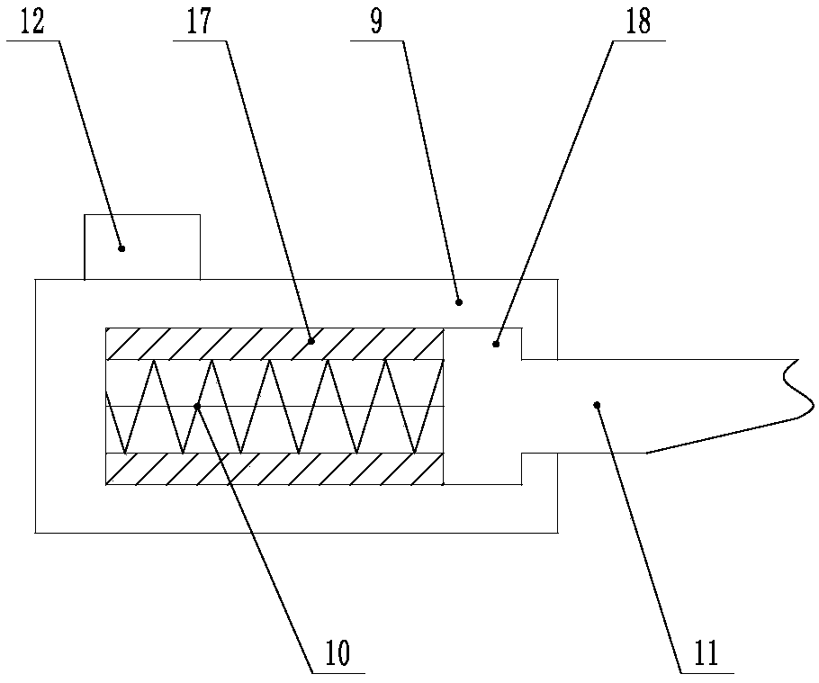
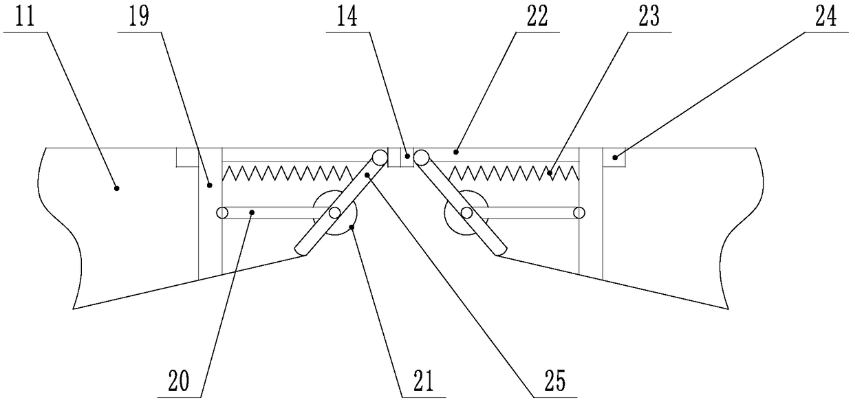
[0039] Step B: Detect the external rainfall through the rain sensor 12. When the detection value of the rain sensor 12 exceeds the preset value, the remote controller controls the hydraulic telescopic mechanism 2 to move upward between the rollers 21 on both sides, and pushes the movable baffle 11 to open , compress the first spring 10 in the fixed groove 9, the second spring 23 is in a compressed state, and the tester body 4 starts to work;

[0040] Step C: After the work of the tester body 4 is completed, the remote controller controls the hydraulic telescopic mechanism 2 to move downward between the rollers 21 on both sides, and the first spring 10 in the fixed groove 9 recovers to deform, so that the movable baffle 11 is folded;

[0041]Step D: When performing mai...

Embodiment 2

[0052] The present invention is based on embodiment 1, and the present invention is further described.

[0053] Such as Figure 1-Figure 2 As shown, the present invention is a method for measuring rainfall in mountainous areas. The bottom of the underground part is set to be inclined, and the lowest part is provided with a water outlet 13, which is convenient for draining the accumulated water in the underground part.

[0054] The hydraulic telescopic mechanism 2 includes a hydraulic cylinder and a piston rod, the hydraulic cylinder is fixed on the base 1, and the placing table 3 is connected to the piston rod.

[0055] One end of the support rod 8 located at the first chute 7 is provided with a limit block 15, the size of the limit block 15 is larger than the opening of the first chute 7, and its effect is to prevent the support rod 8 from falling off from the first chute 7, and the tester Under the action of the support rod 8, the body 4 moves more smoothly.

[0056] The u...


PUM


Abstract

The invention discloses a mountain area rainfall test method. The method comprises the following steps that A) a tester body is installed under the ground surface; B) a rainfall sensor detects the outside rainfall, and when the rainfall exceeds a preset value, a remote controller controls a hydraulic telescoping mechanism to move upwardly between rollers at the two sides; C) after work of the tester body, the remote controller controls the hydraulic telescoping mechanism to move downwardly between the rollers at the two sides; and D) during maintenance, a maintenance staff locates the tester body via a positioner. When it is sunny or the rainfall is relatively low, the tester body is positioned under the ground surface, the tester body and the positioner are enclosed underground by the movable baffle plates at the two upper sides of the test body, sun-scorched and rain-drenched less frequently, and avoided from damage by animals in the surrounding, and thus, the service life of the tester body as well as the positioner is prolonged.

Description

technical field [0001] The invention relates to a rainfall tester, in particular to a method for measuring rainfall in mountainous areas. Background technique [0002] A rain gauge, or rain gauge, rain gauge, is an instrument used by meteorologists and hydrologists to measure the amount of precipitation in an area over a period of time. The rain gauge is composed of a water receiver, a water storage cylinder, and a water storage bottle, and is equipped with a special measuring cup proportional to its caliber. Most rain gauges measure in millimeters and sometimes inches or centimeters. Rain gauge readings can be taken manually or using an automatic weather station, and the frequency of observations can vary according to the requirements of the collecting unit. In most cases the collected rainwater is not retained after observation, but a few weather stations retain samples for pollution levels or other tests. [0003] In order to detect the rainfall in mountainous areas, p...

Claims


Application Information

Patent Timeline
Patent Type & Authority Applications(China)
IPC IPC(8): G01W1/14
CPCG01W1/14
Inventor 李成代
Owner 李成代
Learn More