
Household electronic switch monitoring system

A technology of electronic switch and monitoring system, applied in general control system, control/adjustment system, program control, etc., can solve problems such as difficult operation of air purifiers, kitchen gas leakage, hidden safety hazards, etc., to eliminate hidden safety hazards, Energy-saving and highly intelligent effects

Pending Publication Date: 2019-01-01
六安名家汇光电科技有限公司
View PDF7 Cites 0 Cited by
  • Summary
  • Abstract
  • Description
  • Claims
  • Application Information

AI Technical Summary

Problems solved by technology

Existing switches only have two states of power on and power off. In some cases, it may cause waste and safety hazards, such as forgetting to turn off the lights when falling asleep or forgetting to turn off the switch when the power is off, gas leakage in the kitchen, etc.
In addition, people have higher and higher requirements for the air quality of their residences, and air purifiers have entered more and more families, but how to make reasonable use of air purifiers is difficult to operate

Method used


Image

  • Household electronic switch monitoring system
  • Household electronic switch monitoring system

Examples


Embodiment 1

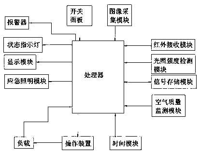
[0016] Such as figure 1 As shown, a household electronic switch monitoring system, which includes a switch panel, a load, a processor and operating components, the switch panel transmits the operating signal to the processor, and the processor controls the action of the operating component, thereby controlling the power on and off of the load , the signal input port of the processor is respectively connected with the image acquisition module, the infrared receiving module, the light intensity detection module, the air quality monitoring module, the load, and the signal storage module, and the signal output port of the processor is connected with a display module and an alarm , an emergency lighting module and a status indicator light, the transmission between the processor and the signal storage module is two-way transmission. The image acquisition module, infrared receiving module, light intensity detection module, air quality monitoring module and display module are respecti...

Embodiment 2

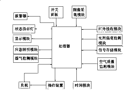
[0019] Such as figure 2 As shown, a household electronic switch monitoring system, which includes a switch panel, a load, a processor and operating components, the switch panel transmits the operating signal to the processor, and the processor controls the action of the operating component, thereby controlling the power on and off of the load , the signal input port of the processor is respectively connected with the image acquisition module, the infrared receiving module, the light intensity detection module, the air quality monitoring module, the load, and the signal storage module, and the signal output port of the processor is connected with a display module and an alarm , an emergency lighting module and a status indicator light, the transmission between the processor and the signal storage module is two-way transmission. The signal input end of the processor is also connected with a gas detection module. The image acquisition module, infrared receiving module, light in...


PUM


Abstract

The invention discloses a household electronic switch monitoring system. The system comprises a switch panel, a load, a processor and an operation component. The switch panel transmits an operation signal to the processor. The processor controls the motion of the operation component so as to control the power on and power off of the load. The signal input port of the processor is connected to an image acquisition module, an infrared receiving module, a light intensity detecting module, an air quality monitoring module, the load, and a signal storage module respectively. The signal output portof the processor is connected with a display module, an alarm, an emergency illumination module, and a state indication lamp. Transmission between the processor and the signal storage module is two-way transmission. In the invention, usage is convenient, an intelligent degree is high, and button operation, remote control operation and intelligent operation can be realized.

Description

technical field [0001] The invention relates to a household electronic switch monitoring system, which belongs to the technical field of electronic switches. Background technique [0002] With the development of science and technology, people have more and more functional requirements for household electrical appliances, correspondingly, the convenience of switching electrical appliances also needs to be changed, and people's requirements for aesthetics are also getting higher and higher. In the prior art, Smart home takes the residence as the platform, household appliances and household appliances as the main control objects, and uses integrated wiring technology, network communication technology, security technology, automatic control technology, audio and video technology to efficiently integrate the facilities related to home life to build an efficient The control and management system of residential facilities and family schedule affairs improves home intelligence, sa...

Claims


Application Information

Patent Timeline
IPC IPC(8): G05B19/048
CPCG05B19/048
Inventor 戴瑞
Owner 六安名家汇光电科技有限公司
Learn More