Design method of aero-engine booster chamber

A technology of aero-engine and design method, which is applied in the field of aero-engine, can solve problems such as unsatisfactory results, restricting the life of thrust bearings, and risks in engine operation

Active Publication Date: 2019-01-01
AECC SHENYANG ENGINE RES INST
View PDF5 Cites 6 Cited by
  • Summary
  • Abstract
  • Description
  • Claims
  • Application Information

AI Technical Summary

Problems solved by technology

However, the results were not entirely satisfactory, which also greatly restricted the life of the thrust bearings and even made the operation of the engine risky

Method used


Image

  • Design method of aero-engine booster chamber
  • Design method of aero-engine booster chamber
  • Design method of aero-engine booster chamber

Examples


Embodiment Construction

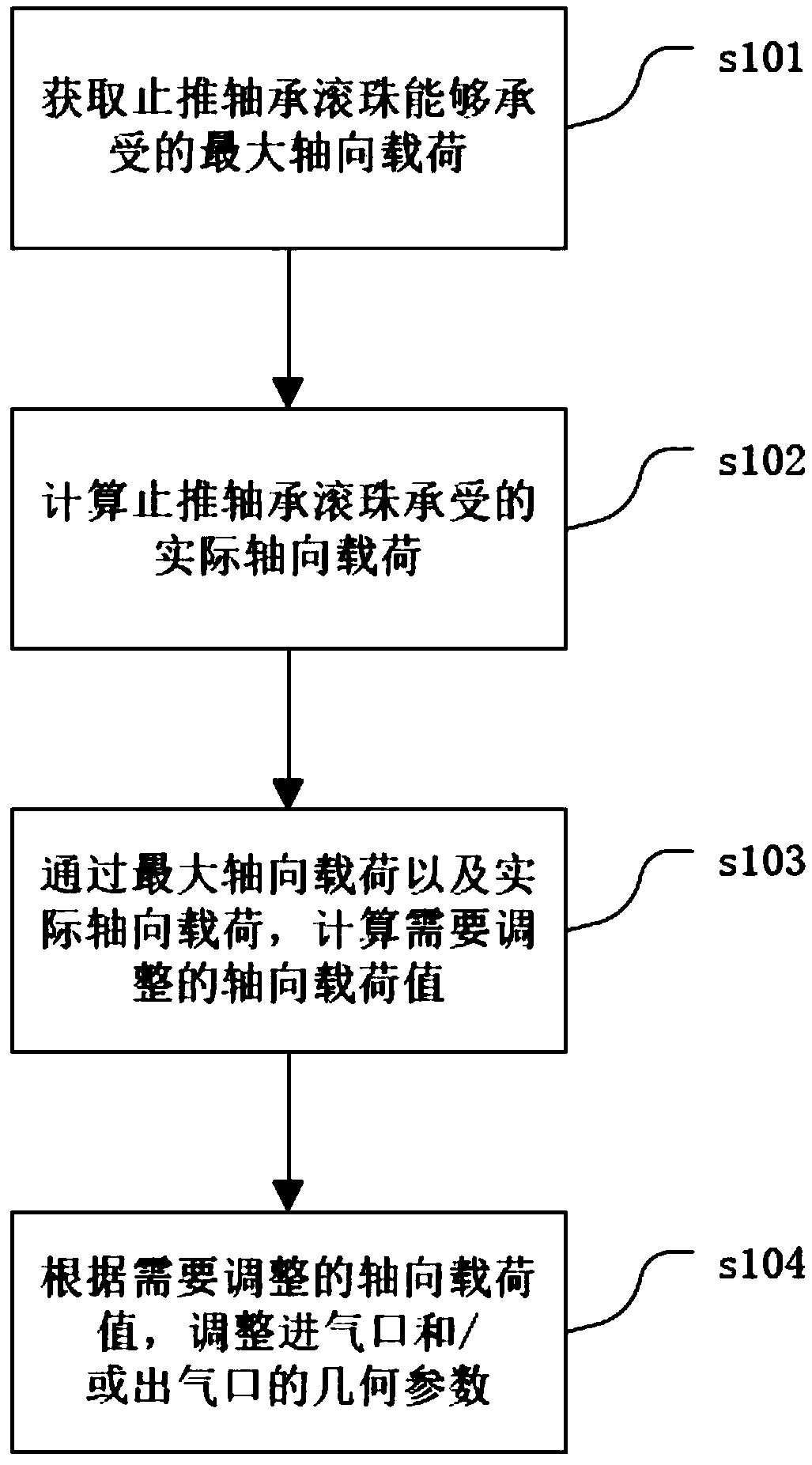
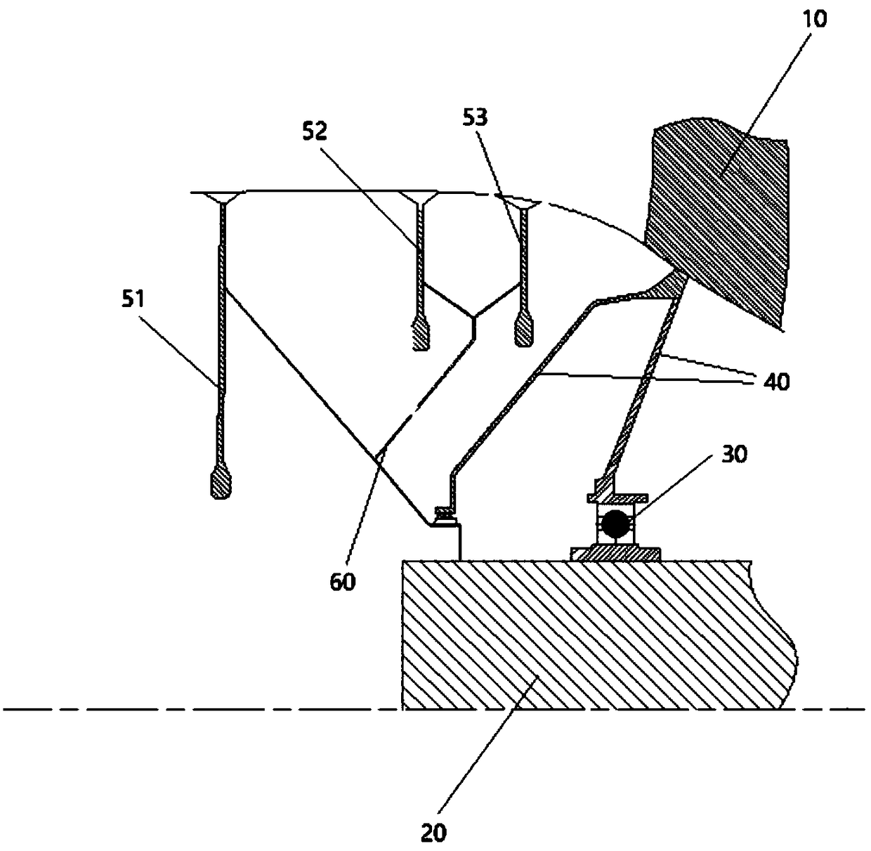
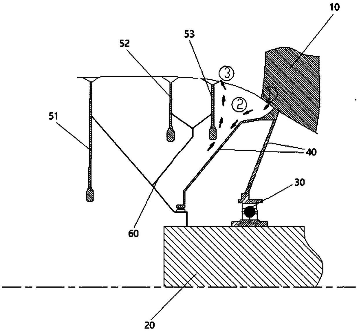
[0019] In order to make the objectives, technical solutions and advantages of the present invention clearer, the technical solutions in the embodiments of the present invention will be described in more detail below in conjunction with the drawings in the embodiments of the present invention. In the drawings, the same or similar reference numerals denote the same or similar elements or elements having the same or similar functions throughout. The described embodiments are some, but not all, embodiments of the invention. The embodiments described below by referring to the figures are exemplary and are intended to explain the present invention and should not be construed as limiting the present invention. Based on the embodiments of the present invention, all other embodiments obtained by persons of ordinary skill in the art without creative efforts fall within the protection scope of the present invention. Embodiments of the present invention will be described in detail below ...


PUM


Abstract

The invention discloses a design method of an aero-engine booster chamber. The design method comprises the following steps: obtaining the maximum axial load that a thrust bearing ball can bear; calculating the actual axial load on thrust bearing balls; through the maximum axial load and the actual axial load, the axial load which needs to be adjusted being calculated; adjusting the geometry of theinlet and / or outlet according to the value of the axial load that needs to be adjusted. By controlling the gas pressure in the booster chamber, the invention can realize the axial force balance welland improve the design margin; moreover, the design of the booster chamber is relatively independent, and regulating the pressure in the chamber has no influence on the realization of other system functions.

Description

technical field [0001] The invention relates to the technical field of aero-engines, in particular to a design method for an aero-engine pressurized chamber. Background technique [0002] As a rotating machine, an aero-engine operates at a speed of 10,000 rpm, which puts extremely high demands on bearing components. Among them, a suitable axial load that can meet the requirements should always be applied to the thrust bearing, so as to ensure that the thrust bearing has sufficient reliable working life, and keep the gap between the rotating and static parts of the engine relatively stable, so that the aero-engine can work Status remains stable. At the same time, it is required that the maximum load borne by the thrust bearing cannot damage it, and that the steel ball of the thrust bearing does not slip destructively on the runway under the minimum load. The axial load borne by the thrust bearing consists of two parts, one part is the axial force of the main passage in the ...

Claims


Application Information

Patent Timeline
Patent Type & Authority Applications(China)
IPC IPC(8): G06F17/50
CPCG06F30/17
Inventor 梁义强刘国朝邓明春周建军
Owner AECC SHENYANG ENGINE RES INST
Why Eureka
Try Eureka